Dahua Technology DH-PFS3125-24ET-190 Podręcznik użytkownika - Strona 10
Przeglądaj online lub pobierz pdf Podręcznik użytkownika dla Przełącznik Dahua Technology DH-PFS3125-24ET-190. Dahua Technology DH-PFS3125-24ET-190 15 stron.
LED
Faceplate
Indicator
Marker
Mode
Control:
You can select the switch mode.
Normal mode (Normal): Switch all ports can communicate with each other
Port isolation mode (VLAN): 1 to 24 cannot communicate with each other, but can
communicate with the uplink Combo port 25.
Monitoring mode (Monitor): 1 to 8 ports support port priority, optimize port cache, switch all
ports can communicate with each other.
Network extend mode(Extend): 1 to 8 port rate down to 10Mbps, the farthest transmission
distance of up to 250 meters, all ports can communicate with each other.
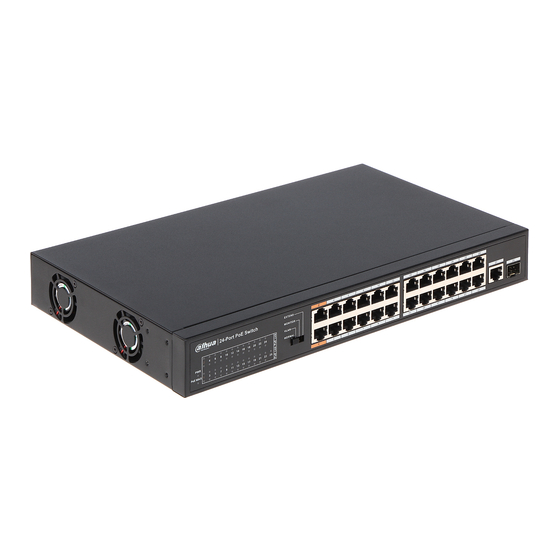
10/100 Mbps RJ-45 ports (1~24):
Designed to connect to the device with a bandwidth of 10Mbps, 100Mbps. Each has a
corresponding Link/Act and PoE indicator.
10/100/1000Mbps RJ45 port 25:
Designed to connect to the device with a bandwidth of 10Mbps, 100Mbps or 1000Mbps. Each
has a corresponding Link/Act LED.
1000Mbps SFP port 25:
Designed to install the SFP module. The Switch features one SFP transceiver slots that are
shared with one associated RJ45 ports. A SFP port and an associated RJ45 port are referred to
as "Combo" port, which means they cannot be used simultaneously, and only SFP port work or
only RJ45 port work at the same time.
1.3.2 Rear Panel
The rear panel of the Switch contains one Grounding Terminal, Heat vent and AC power
connector shown as below.
Grounding Terminal:
Located on the left side of the power supply connector, use wire grounding to lightning
protection.
Heat vent:
The Heat vent is located in the middle position of the rear panel of the switch. It is used for heat
dissipation and ventilation. Do not cover it.
AC Power Connector :
Status
Indication
successfully.
Figure 1-3
Rear panel
Introduction 3