Advanced Air 0160 Series Instrukcja instalacji, obsługi i konserwacji - Strona 9
Przeglądaj online lub pobierz pdf Instrukcja instalacji, obsługi i konserwacji dla Tłumiki ognia i dymu Advanced Air 0160 Series. Advanced Air 0160 Series 13 stron. Air control fire damper
Również dla Advanced Air 0160 Series: Skrócona instrukcja obsługi (14 strony)

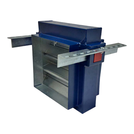
FIRE – 0160 DRYWALL PLATE INSTALLATION FOR FLEXIBLE SUPPORTING CONSTRUCTION
M10 drop rod
Cleat
Drywall plate
Access door for
inspection / damper reset
0160 W/ DRYWALL PLATE
PRODUCT
2019 EFECTIS R002230
CLASSIFICATION REPORT NO.
TESTED INSTALLATION METHOD SHOWN. DIFFERING INSTALLATION METHODS TO THIS MUST BE APPROVED BY THE BUILDING CONTROL AUTHORITY (BCA) BEFORE PROCEEDING.
Preparation
1
2
3
Two layers of 50mm thick
Installation sequence
140kg/m fire batt
4
5
6
0160 Series fire damper
7
8
9
10
11
12
Two hour rated flexible
13
supporting construction
to BS EN 1363-1:2020
14
Steel stud depth – 71 to 100mm
15mm thick gypsum boards
FLEXIBLE SUPPORTING CONSTRUCTION
APPLICATION
E120 (VE I O)
CLASSIFICATION
Nominal duct width
Ensure that the damper is kept
in a clean dry environment and
Nominal duct height
that there is no damage to the
damper.
Remove all the packaging and
transit ties before installation.
Work out the opening size to be
cut using the adjacent table.
The drywall will consist of two layers of 15mm plasterboard each side of steel studwork with an
optional mineral wool insulation. The opening will be a letterbox construction with overlapping layers
of plasterboard with an opening clearance around the damper casing in line with the above table.
Two M10 drop rods per fire damper shall be fitted on one side of the drywall. These should be securely
installed in line with the manufacturer's fixing instructions in a position to match the cleats on the dry
wall damper frame.
The drop rods should have a nut screwed on for clamping the cleat from above.
The damper should be mounted centrally in the opening flush with the dry wall frame on the side with
the drop rods, as detailed in the drawing. The drop rods are to slide through the holes in the cleats
and a nut screwed on to take the support of the damper. The damper must then be levelled and when
in the correct position the nut above the rail should be tightened against the cleat.
The galvanised mild steel ductwork connecting to the damper spigots must overlap by up to 40mm,
leaving a minimum 10mm clearance for any duct expansion in a fire situation.
The galvanised mild steel ductwork connections must be sealed with an approved galvanised mild
steel ductwork sealer and fixed with low resistance fixings such as aluminium rivets that will melt at
high temperature allowing the duct to break away without effecting the integrity of the installation.
The connecting galvanised mild steel ductwork must be independently supported within one metre of
the connections and have been installed in accordance with DW144.
The gap between the damper and the wall opening will need filling with two layers of 50mm thick
140kg/m3 fire batt cut to an interference fit and pushed in to place. All cut edges must be sealed with
a firebatt sealant to BS EN 13501-2. A fire rated intumescent mastic (to BS EN 13501-2) shall be applied
to each joint.
An access door should be fitted on the access side of the damper to enable the resetting of the
damper blades.
When the damper installation has been completed checks should be made to ensure the drop rods
are secured to the cleats and there is no movement, operation of the damper should be checked.
Complete DW145 Fire Damper Certificate.
Opening width maximum
100-1,000mm
Nominal duct +90mm
Opening height maximum
100mm
Nominal duct +90mm
101-300mm
Nominal duct +115mm
301-525mm
Nominal duct +140mm
526-700mm
Nominal duct +165mm
701-925mm
Nominal duct +190mm
926-1,000mm
Nominal duct +215mm
9
