Advanced Amplifiers AA-1218G-3.5KW-PT Podręcznik użytkownika - Strona 4
Przeglądaj online lub pobierz pdf Podręcznik użytkownika dla Wzmacniacz Advanced Amplifiers AA-1218G-3.5KW-PT. Advanced Amplifiers AA-1218G-3.5KW-PT 14 stron. R.f. microwave amplifier system

Prime power is connected to the TWTA unit via the three prong socket in the rear of the enclosure. It is
fused and controlled by the Main Relay.
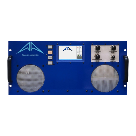
The Front Panel Switches control the TWTA. The WARM UP button controls the Main Relay to power
the unit. The STANDBY, OPERATE and RESET buttons control various stages of the unit operation.
The Front Panel Display shows current status of the unit and allows to change certain parameters.
The computer interface, specified at time of manufacture, allows the user to emulate the STANDBY,
OPERATE and RESET buttons remotely as well as read status of the unit and change amplifier's
settings and parameters. It also allows to set the internal video pulse generator.
The Low Voltage Power Supply provides regulated and filtered low voltages to various components
within the TWTA. It also contains a microprocessor to monitor cooling fan currents.
The TWT is connected to the external termination points with various RF configurations specified at
time of manufacture.
Locate amplifier in such a manner that adequate cool air is available to the fan inlet on the front of the
unit. Do not restrict space in the back of the unit such that exhaust air is confined or blocked.
Properly terminate both RF input and RF output with appropriate RF components and at appropriate
drive and frequency levels.
Connect AC power to appropriate voltage and frequencies only, with 15 amp service minimum and
adequate gauged wiring (12AWG recommended).
Safety ground in connecter must be used, and, for 120vac applications, Line and Neutral must not be
reversed. If reversed, the unit will not function.
Output sample –40 dB - Provides a sample of the output power at a 40 dB reduction for power
•
monitoring and spectral analysis.
Input sample –20 dB - Provides a sample of the input power at a 20 dB reduction for power
•
monitoring and spectral analysis.
Interstage sample –20 dB - A sample of the RF stream between the Solid State Amplifier and
•
the TWT at a 20 dB reduction. Provides a means of TWT gain calibration.
Detected video output - A crystal-detected representation of the RF output power.
•
General System Introduction
Installation
TWTA connections
Page 4 of 14
