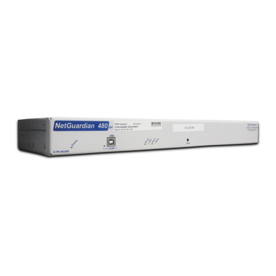
DPS Telecom NetGuardian 480 Podręcznik użytkownika - Strona 6
Przeglądaj online lub pobierz pdf Podręcznik użytkownika dla Przyrządy pomiarowe DPS Telecom NetGuardian 480. DPS Telecom NetGuardian 480 16 stron. Unable to configure netguardian ip address via usb craft port
Również dla DPS Telecom NetGuardian 480: Techno Knowledge Paper (10 strony)

3
3
Power and Data Connections
Pow er Input
Pow er Output
Fig. 2. Power input and output
The Test Fixture has two power connections. If one is looking at the control panel of the Test Fixture, the left-hand power
connection, nearest to the Analogs 7–8 connector, is a power input providing power to the Test Fixture; the right-hand power
connection is a power output providing power to the NetGuardian unit connected to the Test Fixture. Refer to Figure 2, above.
The relays will only work if the NetGuardian unit is powered from the Power Out of the NetGuardian Test Fixture. Additionally,
both Amphenol connectors need to be connected in order for the relay LED indicators to come on.
Fig. 3. Connections between the Test Fixture and a NetGuardian. Be sure to connect both Amphenol cables before operating,
otherwise certain components may not operate correctly (such as relay LEDs).
Data connections between the Test Fixture and the NetGuardian unit to be tested are shown in Figure 3, above.
Data connections between the Test Fixture and the NetGuardian must be made before power is applied.
To connect the Test Fixture's power and data connections, follow these steps:
1. Make sure that the source power supply is off.
2. Disconnect the power input lead from the NetGuardian unit and connect it to the power input on the NetGuardian Test
Fixture.
3. Connect the NetGuardian unit to be tested to the Test Fixture's power output using the provided DC power cable. The
NetGuardian unit must be powered from the Test Fixture, or certain components (such as Relay LEDs) will not operate
properly.
