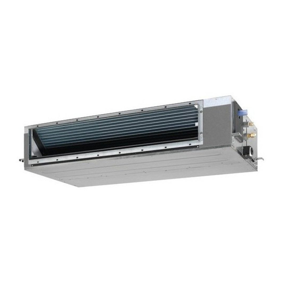
Daikin ADEQ50C2VEB Instrukcja instalacji - Strona 8
Przeglądaj online lub pobierz pdf Instrukcja instalacji dla Klimatyzator Daikin ADEQ50C2VEB. Daikin ADEQ50C2VEB 16 stron. Siesta
split system air conditioners
Również dla Daikin ADEQ50C2VEB: Instrukcja obsługi (8 strony)

Drain piping work
Installation of drain piping
Install the drain piping as shown in the figure and take measures
against condensation. Improperly rigged piping could lead to leaks
and eventually wet furniture and belongings.
Install the drain pipes.
-
Keep piping as short as possible and slope it downwards at a
gradient of at least 1/100 so that air may not remain trapped
inside the pipe.
-
Keep pipe size equal to or greater than that of the connecting
pipe (vinyl pipe of 20 mm nominal diameter and 26 mm outer
diameter).
-
Push the supplied drain hose as far as possible over the
drain socket.
Drain pipe connection hole
Connect the drain pipe after
removing the rubber cap and
insulation tubing attached to
the connection hole.
1
1
Drain socket (attached to the unit)
2
Drain hose (supplied with the unit)
-
Tighten the metal clamp until the screw head is less than
4 mm from the metal clamp part as indicated in the
illustration.
3
4
A
A'
1
1
Drain socket (attached to the unit)
2
Drain hose (supplied with the unit)
3
Metal clamp (supplied with the unit)
4
Large sealing pad (supplied with the unit)
5
Drain piping (field supply)
-
Wrap the supplied large sealing pad over the metal clamp
and drain hose to insulate and fix it with clamps.
-
Insulate the complete drain piping inside the building (field
supply).
-
If the drain hose cannot be sufficiently set on a slope, fit the
hose with drain raising piping (field supply).
5
Refrigerant pipes
2
A-A'
4 mm
3
4
1
2
2
5
After piping work is finished, check drainage flows
smoothly.
•
Gradually insert approximately 1L of water into the drain pan
to check drainage in the manner described below.
• Gradually pour approximately 1L of water from the outlet
hole into the drain pan to check drainage.
• Check the drainage.
Air outlet
Portable pump
Bucket
When electric wiring work is finished
Check drainage flow during COOL running, explained in
operation" on page
8.
When electric wiring work is not finished
Remove the switch box cover and connect the single-phase
power supply and the remote controller to the terminals. (Refer
to chapter
"Electric wiring work" on page 6
attachment/detachment) (Refer to
Connect the single-phase power supply to connections 1 and 2
(as shown in the figure) on the power supply terminal board and
confirm drain operation.
1 2 3
L N
Be aware that the fan will turn during the operation.
Drain outlet
Refrigerant pipes
"Test
for switch box
figure 9
and 10)
L N
