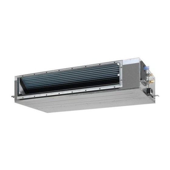
Daikin ADEQ71C2VEB Instrukcja instalacji - Strona 7
Przeglądaj online lub pobierz pdf Instrukcja instalacji dla Klimatyzator Daikin ADEQ71C2VEB. Daikin ADEQ71C2VEB 16 stron. Siesta
split system air conditioners
Również dla Daikin ADEQ71C2VEB: Instrukcja obsługi (8 strony)

-
Be sure to insulate the duct to prevent condensation
from forming. (Material: glass wool or polyethylene
foam, 25 mm thick)
-
Use electric insulation between the duct and the wall
when using metal ducts to pass metal laths of the net or
fence shape or metal plating into wooden buildings.
-
Be sure to explain about the way of maintaining and
cleaning local procurements (air filter, grille (both air
outlet and suction grille), etc.) to your customer.
Refrigerant piping work
For refrigerant piping of outdoor unit, refer to the installation manual
supplied with the outdoor unit.
Execute heat insulation work completely on both sides of the gas
piping and the liquid piping. Otherwise, this can sometimes result in
water leakage.
Before rigging tubes, check which type of refrigerant is used.
Installation shall be done by a licensed refrigeration
technician, the choice of materials and installation shall
comply with the applicable national and international
codes. In Europe, EN378 is the applicable standard that
shall be used.
Use a pipe cutter and flare suitable for the used refrigerant.
To prevent dust, moisture or other foreign matter from infiltrating
the tube, either pinch the end, or cover it with tape.
Use copper alloy seamless pipes (ISO 1337).
The outdoor unit is charged with refrigerant.
To prevent water leakage, execute heat insulation work
completely on both sides of the gas and liquid piping. When
using a heat pump, the temperature of the gas piping can reach
up to approximately 120°C, use insulation which is sufficiently
heat resistant.
Be sure to use both a spanner and torque wrench together when
connecting or disconnecting pipes to/from the unit.
1
Torque wrench
2
Spanner
3
Piping union
4
Flare nut
Do not mix anything other than the specified refrigerant, such as
air, etc..., inside the refrigerant circuit.
Use annealed material only for flare connections.
Refer to
Table 1
for the dimensions of flare nut spaces and the
appropriate tightening torque. (Overtightening may damage the
flare and cause leaks.)
Table 1
Pipe
Tightening torque
gauge
(N•m)
Ø6.4
15~17
Ø9.5
33~39
Ø12.7
50~60
Ø15.9
63~75
When connecting the flare nut, coat the flare inner surface with
ether oil or ester oil and initially tighten 3 or 4 turns by hand
before tightening firmly.
If the refrigerant gas leaks during the work, ventilate the area. A
toxic gas is emitted by the refrigerant gas being exposed to a fire.
1
2
3
4
Flare dimension
A (mm)
Flare shape
8.7~9.1
90° ±2
12.8~13.2
A
16.2~16.6
R0.4~0.8
19.3~19.7
Make sure there is no refrigerant gas leak. A toxic gas may be
released by the refrigerant gas leaking indoor and being
exposed to flames from an area heater, cooking stove, etc.
Finally, insulate as shown in the figures below.
Piping insulation procedure
Gas piping
1
6
3
2
6
4
A
C
B
7
D
1
Piping insulation material (field supply)
2
Flare nut connection
3
Insulation for fitting (delivered with the unit)
4
Piping insulation material (main unit)
5
Main unit
6
Clamp (field supply)
7
Medium 1 sealing pad for gas piping (delivered with the unit)
Medium 2 sealing pad for liquid piping (delivered with the unit)
A
Turn seams up
B
Attach to base
C
Tighten the part other than the piping insulation material
D
Wrap over from the base of the unit to the top of the flare nut
connection
For local insulation, be sure to insulate local piping all
the way into the pipe connections inside the unit.
Exposed piping may cause condensation or may
cause burns when touched.
Cautions for brazing
Be sure to carry out a nitrogen blow when brazing.
Brazing without carrying out nitrogen replacement or releasing
nitrogen into the piping will create large quantities of oxidized
film on the inside of the pipes, adversely affecting valves and
compressors in the refrigerating system and preventing normal
operation.
When brazing while inserting nitrogen into the piping, nitrogen
must be set to 0.02 MPa with a pressure-reducing valve (=just
enough so that it can be felt on the skin).
1
2
6
1
Refrigerant piping
2
Part to be brazed
3
Taping
4
Hands valve
5
Pressure-reducing valve
6
Nitrogen
Liquid piping
1
6
3
2
6
5
A
C
7
D
3
4
5
6
4
5
B
4
