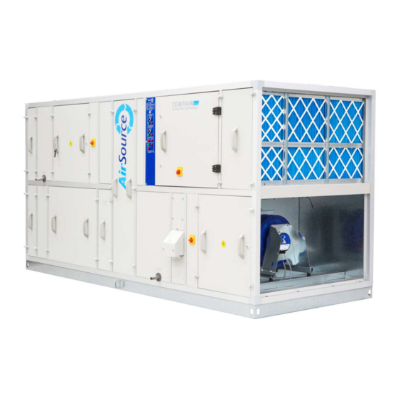
AirSource TempAir Instrukcja instalacji, obsługi i konserwacji - Strona 7
Przeglądaj online lub pobierz pdf Instrukcja instalacji, obsługi i konserwacji dla Centrale wentylacyjne AirSource TempAir. AirSource TempAir 20 stron. Air handling units, airsource heatpumps

INSTALLATION
General
All units must be installed in accordance with good engineering standards, upright
All units must be installed in accor
and level on a prepared base. Fixing down of air handling units is at the discretion of
level on a prepared base. Fixing down of air handling units is at the discretion of
level on a prepared base. Fixing down of air handling units is at the discretion of
the installer and dependant of the site conditions. Flexible connections are NOT
the installer and dependant of the site conditions. Flexible connections are NOT
the installer and dependant of the site conditions. Flexible connections are NOT
recommended for connecting ductwork to the unit, as the fan outlet is fitted with a
recommended for connecting ductwork to t
flexible connector and is isolated from the unit via anti-vibration mounts. Provision
flexible connector and is isolated from the unit via anti
must be made for a cleanable drain trap which should terminate at an open drain or
must be made for a cleanable drain trap which should terminate at an open drain or
must be made for a cleanable drain trap which should terminate at an open drain or
tundish which will ensure any blockage can be seen and remedied. Units that are
tundish which will ensure any blockage can
delivered in sections should be carefully checked with the general arrangement
delivered in sections should be carefully checked with the general arrangement
delivered in sections should be carefully checked with the general arrangement
drawings to ensure erection in the correct sequence and handing. The sections would
drawings to ensure erection in the correct sequence and handing. The sections would
drawings to ensure erection in the correct sequence and handing. The sections would
be bolted together as detailed on page 8. Site wiring must not penetrate or restrict
be bolted together as detailed on page 8. Site wiring mu
opening or removal of access panels.
opening or removal of access panels.
Locating Equipment
It is important to ensure that adequate access is provided around the perimeter of the
It is important to ensure that adequate access is provided around the perimeter of the
It is important to ensure that adequate access is provided around the perimeter of the
AHU for maintenance purposes as follows:
maintenance purposes as follows:
Access Side of Unit
Sufficient room at the access side of the unit is required for removal of the largest
component within the AHU
Back of Unit
Double width units require access to the front and back, therefore access requirements
Double width units require access to the front and back, therefore access requirements
Double width units require access to the front and back, therefore access requirements
apply as above. Where access to components is not required at the back of the unit we
apply as above. Where access to components is not require
recommend a minimum of 500mm is provided.
recommend a minimum of 500mm is provided.
Air Intake/Discharge
Allow sufficient room for cowls to fit (dimensions as detailed on the general
Allow sufficient room for cowls to fit (dimensions as detailed on the general
Allow sufficient room for cowls to fit (dimensions as detailed on the general
arrangement drawing). We also recommend an additional distance equal to the unit
arrangement drawing). We also recommend an additional distance equal to the unit
arrangement drawing). We also recommend an additional distance equal to the unit
width before any obstacle to prevent recirculation of the exhaust air into the fresh air
dth before any obstacle to prevent recirculation of the exhaust air into the fresh air
dth before any obstacle to prevent recirculation of the exhaust air into the fresh air
inlet.
m at the access side of the unit is required for removal of the largest
m at the access side of the unit is required for removal of the largest
t within the AHU.
ineering standards, upright
he unit, as the fan outlet is fitted with a
vibration mounts. Provision
be seen and remedied. Units that are
st not penetrate or restrict
d at the back of the unit we
Minimum 500mm
for access
Air intake/discharge
ischarge
gap equal to unit width
ap equal to unit width
Installation, Operation & Maintenance Manual
stallation, Operation & Maintenance Manual
6
