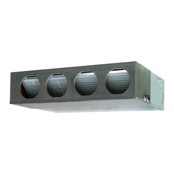
AirStage ARXB45GALH Instrukcja instalacji - Strona 11
Przeglądaj online lub pobierz pdf Instrukcja instalacji dla Klimatyzator AirStage ARXB45GALH. AirStage ARXB45GALH 18 stron. Indoor unit (duct type)

Tightening torque
M3 screw
(Transmission /X1, X2)
(Remote controller /Y1, Y2, Y3)
To peel the fi lm from the lead cable, use a dedicated tool that will not damage the
conductor cable.
When installing a screw on the terminal block, do not cut the cable by overtightening
the screw. On the other hand, an undertightened screw can cause faulty contact, which
will lead to a communication failure.
6.4. Connection of wiring
(1) Remove the control box cover and install each connection cable.
(2) After wiring is complete, secure the remote controller cable, connection cable, and
power cable with the cable clamps.
Power supply cable
(Field supply)
Cable tie (Medium)
(Accessories)
L, N:Power supply cable
Cable clamp
Cable tie (Medium) (Accessories)
When switching the DIP switch (SW1), be sure to turn off the power supply to the
indoor unit. Otherwise, the PC board of the indoor unit may be damaged.
0.5 to 0.6 N·m
(5 to 6 kgf·cm)
CAUTION
Control box cover
Screw
Remote control-
ler cable, Trans-
mission cable
(Field supply)
X1, X2:
Remote controller cable
Transmission cable
Y1:Red
Y2:White
Y3:Black
CAUTION
Remote controller cable
For 2-wire type
Y1:Non-poler
Connect the remote
Y2:Non-poler
controller cable
Y3:Do not connect *1
Set the DIP switch
2WIRE
(SW1)
(Factory setting)
*1: If you connect the remote controller cable to the terminal
Y3, 2-wire type remote controller does not work.
6.5. Air fl ow changing
When using the ARXB24/30/36/45L model with external Static Pressure under 40 Pa,
the Wire (FAN MOTOR) must be replaced as explained below.
Replacement method
(1) Remove the cover.
(2) Remove the Wire (TYPE A) connector from Wire (FAN MOTOR).
(3) Remove the Wire (TYPE A) connector from CN110 of the PCB.
(4) Insert the Wire (TYPE B) connector into CN110 of the PCB.
(5) Insert the Wire (TYPE B) connector into Wire (FAN MOTOR).
(6) Insert the cover.
Cover
External Static Pressure and Required Connector Type
Type
External Static
40 to 80 Pa
Pressure
Wire
ARXB24
ARXB30
ARXB36
1 BLACK
2 WHITE
3 RED
4 BLUE
5 PINK
6 PURPLE
Factory setting
Remark
(Standard static pressure)
] 1
For 3-wire type
Y1:Red
Y2:White
Y3:Black
DIP switch
(SW1)
3WIRE
Wire
(Fan motor)
A
B
0 to 40 Pa
ARXB45
1 BLACK
1 BLACK
2 WHITE
2 WHITE
3 PINK
3 RED
4 PURPLE
4 PINK
5 PURPLE
5 BLUE
6 BLUE
Accessories
(Low static pressure)
En-10
