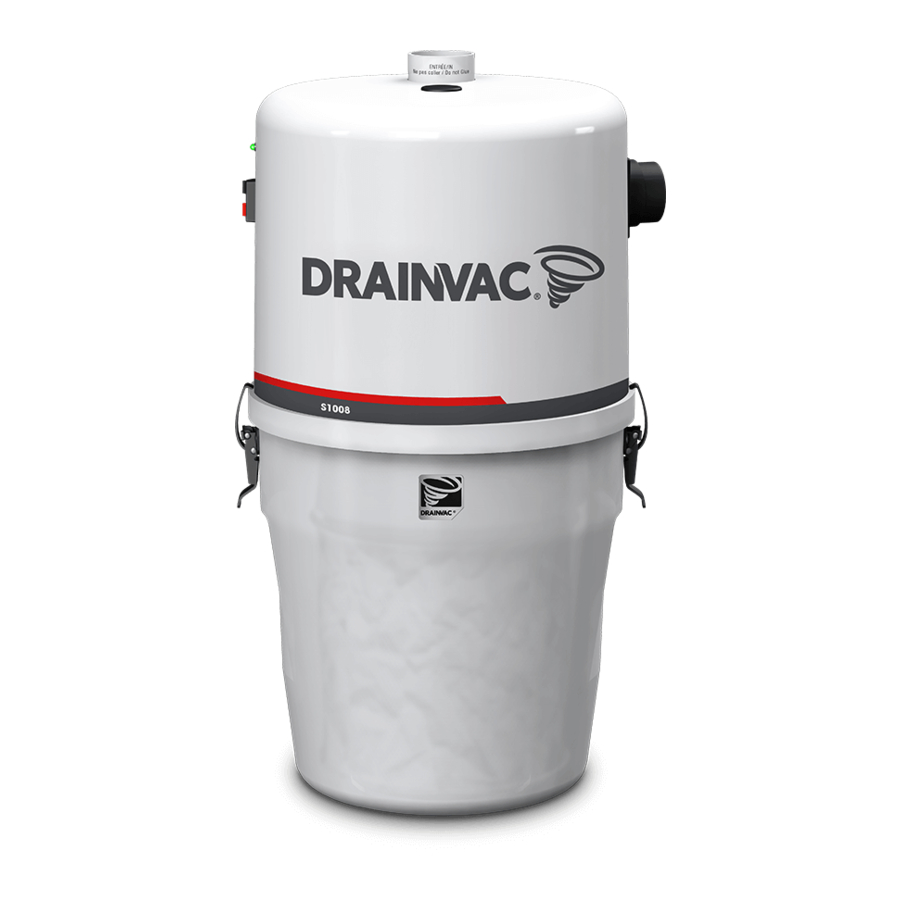
Drainvac G2E-007i-M Instrukcja obsługi - Strona 10
Przeglądaj online lub pobierz pdf Instrukcja obsługi dla Centralne systemy próżniowe Drainvac G2E-007i-M. Drainvac G2E-007i-M 18 stron.

ACTIVAC 3 AND MUFFLER INSTALLATION
An Activac 3 filter and an exhaust muffler are included with the S1000 and G2 series. If
you have purchased the Pro series, they are sold separately.
An Activac 3 filter is not suitable for a two-motor unit. An air outlet leading
outside the building is mandatory for these models.
ACTIVAC 3 - ONE-MOTOR SERIES ONLY
Clamp the 90
short elbow to the unit
o
with the supplied collar and insert the
Activac 3 filter to the other end with a
second collar (do not glue).
MUFFLER
Connect the air outlet to the unit, securing it with a clamp and install the muffler with
a second collar (do not glue).
The 90
elbow can be replaced by a straight pipe.
o
Simple motor
18
Double motor
The following pages illustrate piping diagrams, typical installations and the parts
that we recommend for an optimum performance of your central vacuum system.
GENERAL INFORMATION
An air outlet leading outside must always be installed on a two-motor unit.
•
Make sure that the evacuated air does not lead under a carport.
• If your unit includes two motors, it is important to use metal piping and couplings
for the air outlet.
• To determine where to locate the wall inlets, use the length of the vacuum hose as
a basis, measuring the furthest point from the wall where the wall inlets are to be
installed. Do the same for all the wall inlets until all areas of the house or building
can be reached with the vacuum hose, by moving it from one wall inlet to another;
don't forget to install one in the garage or outside to vacuum your car.
• If your walls are made of gypsum board, never install a wall inlet in the centre
of the wall. Drill the holes for the wall inlets close to a wall stud or a door frame.
• Any screw length can be used if you install the piping as illustrated in Figure A.
• If you install the piping as illustrated in Figure B, make sure to position the small
screw in the right place to avoid piercing a hole through the pipe.
• Always use a short elbow when connecting the wall inlets (Figures A and B) to
prevent long objects (for example, a pencil) that may have been vacuumed by
mistake from blocking the piping further on.
Short elbow
Figure A
PIPING INSTALLATION
Small screw
Figure B
19
