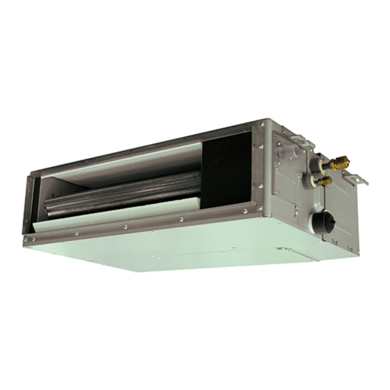
AirStage ARXK24GALH Instrukcja instalacji - Strona 8
Przeglądaj online lub pobierz pdf Instrukcja instalacji dla Klimatyzator AirStage ARXK24GALH. AirStage ARXK24GALH 19 stron. Indoor unit (duct type)

5. INSTALLING DRAIN PIPES
Do not insert the drain piping into the sewer where sulfurous gas occurs. (Heat
exchange erosion may occur)
Insulate the parts properly so that water will not drip from the connection parts.
Check for proper drainage after the construction by using the visible portion of
transparent drain port and the drain piping fi nal outlet on the body.
Do not apply adhesive agent on the drain port of the body.
(Use the attached drain hose and connect the drain piping)
5.1A. ARXK**GCLH model
• Use general hard polyvinyl chloride pipe (VP25) [outside diameter 32 mm].
• Do not perform a rise, trap and air bleeding.
• Provide a downward gradient (1/100 or more).
• Provide supporters when long pipes are installed.
• Use an insulation material as needed, to prevent the pipes from freezing.
• Install the pipes in a way that allows for the removal of the control box.
GOOD
Locally arranged pipe
Max. 300 mm
PROHIBITED
Observe the following procedures to construct centralized drain pipe fi ttings.
VP30 or more [O.D 38 mm or more]
700 mm or less
En-7
WARNING
CAUTION
Gap of 1.5 to 2 m
VP25 [O.D
32 mm or more]
700 mm or less
Horizontal or
upward gradient
Air bleeding
Rise
Trap
Downward gradient 1/100 or more
5.1B. ARXK**GALH model
• When using the drain port on the left side of the unit, remove the drain cap and install it to
the right side drain port.
Unit
• Use general hard polyvinyl chloride pipe (VP25) [outside diameter 32 mm].
• Do not perform a rise, trap and air bleeding.
• Provide a downward gradient (1/100 or more).
• Provide supporters when long pipes are installed.
• Use an insulation material as needed, to prevent the pipes from freezing.
• Install the pipes in a way that allows for the removal of the control box.
GOOD
Supporter
100 mm or more
PROHIBITED
Observe the following procedures to construct centralized drain pipe fi ttings.
5.2. Install the drain pipe
(1) Be sure to use supplied Drain hose 1 and Hose band 2
Drain
hole
Drain cap
Downward gradient
2.5 to 5.0 mm
Locally arranged pipe
Air bleeding
VP30 or more
Downward gradient
[O.D 38 mm or more]
1/100 or more
2 Hose band (Accessories)
1 Drain hose (Accessories)
Hose band
4 mm or less
20 mm
Gap of 1.5 to 2 m
Supporter
VP25 [O.D 32 mm
or more]
Trap
Rise
Hard PVC side
