Carlin 51300AS Instrukcja instalacji i obsługi - Strona 4
Przeglądaj online lub pobierz pdf Instrukcja instalacji i obsługi dla Wentylator Carlin 51300AS. Carlin 51300AS 8 stron. Cap system kit, combustion air proving kit with burner cut-off
The CAP System is designed to shut down the burner in the event the outside combustion air supply becomes blocked. At each
burner startup, the system will check the air intake during pre-purge (Valve Delay On*). If the air is blocked, the control will abort
ignition and shutdown the burner. If the air intake is not blocked during this startup test, but becomes blocked during normal burner
operation, the burner will shut down if the air remains blocked for 20 seconds. Following any shutdown, the burner will be permitted
to recycle 3 times following a 1 minute delay. The system will lock out the burner if the blockage continues throughout 3 recycles
during any single call for heat.
* If the Burner has no valve, the air intake cannot be checked during pre-purge. In this case, the burner will shut down following the
20 second blockage described above. For all burners with valves, Valve Delay settings of less than 15 Seconds will be automatically
changed to 15 Seconds to allow for the prepurge test.
Getting Started
1
Ensure you have the right CAP System Kit for your applica-
tion by confirming the firing rate (in GPH) with the table on
page 1.
IMPORTANT: If you change the firing rate, pressure
switches are available separately to convert the CAP
System after installation. (See instructions for Installing
Pressure Switch on page 8).
Pressure Switch Conversion
Firing Rate GPH
0.50-1.00
1.05-1.45
1.50-1.90
2
Ensure that the burner is equipped with a
Carlin Pro-X 70200 primary control with low voltage
blocked vent (BV) terminals as shown.
NOTE: 70200 controls
manufactured prior
to Sept. 2018
are not
compatible
with the
CAP System.
CAP System Operation
Pressure Switch
50806A
50806B
50806C
3
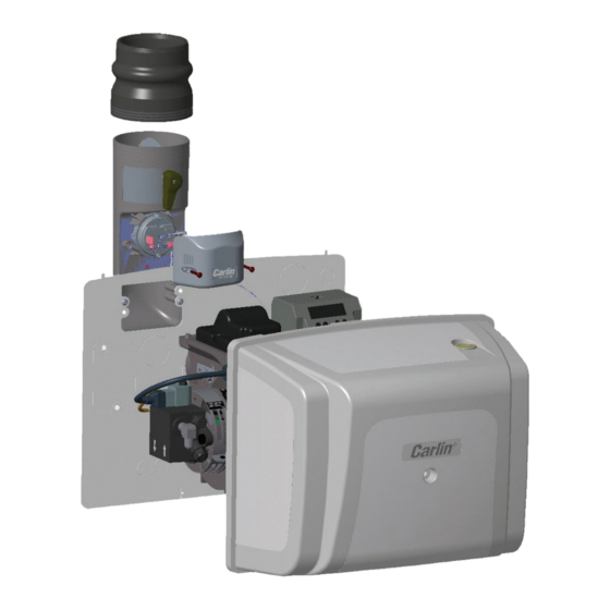
INSTALLING BACKPLATE (for uncovered burners)
If installing on a covered burner, skip to Step 4.
•
• Mount backplate
2
•
to the burner using the mounting bolts and star wash-
ers
provided (as shown). The backplate is reversible to
9
accommodate left-hand or right-hand mounting of the air
inlet. (See step 8 for available inlet mounting configura-
tions.)
• Reroute any BX cable, wiring harness, etc. through one
of the circular knockouts in the backplate
4
ROUTE THE OIL LINE
• Route the oil line through one of the circular knockouts in
the burner cover backplate
5
REMOVE AIR INLET KNOCKOUT
• Remove the 2" x 4" air inlet knockout that corresponds
to the desired air inlet position (vertical or horizontal) as
shown in step 8.
4
in the desired orientation and secure
•
.
2
•
.
2