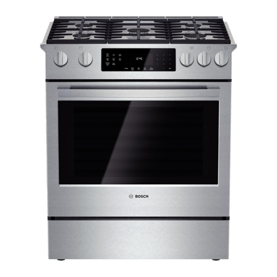
Bosch Vision 800 Series Instrukcja serwisowa - Strona 20
Przeglądaj online lub pobierz pdf Instrukcja serwisowa dla Piekarnik Bosch Vision 800 Series. Bosch Vision 800 Series 43 stron. Gas slide-in ranges
Również dla Bosch Vision 800 Series: Instrukcja obsługi (40 strony), Wymiary i specyfikacje (2 strony), Instrukcja instalacji (6 strony), Instrukcja instalacji (28 strony), Instrukcja serwisowa (36 strony)

58300000202443_ARA_EN_C
There is a Door Lock Relay Test available in Service mode. See the
Service Mode section for details.
6.2.1
Replacing the Latch/Motor Assembly
1. Remove power to the oven.
2. Remove the inner screws securing the latch to the latch plate,
then remove the outer screws securing the latch plate to the
oven.
Figure 20 Front latch plate; remove/replace screws in order shown
3. Hold the latch hook and slide the latch assembly a little to the
left to disengage it from the small support bracket that sits
directly behind it, then pull the latch forward.
Figure 21 Door latch/motor assembly and rear support bracket
Copyright by BSH Home Appliances Corporation
This material is intended for the sole use of BSH authorized persons and may contain confidential and proprietary information. Any unauthorized review, use, copying, disclosure, or distribution in any format is prohibited.
JANUARY 2018
4. Disconnect the wires.
5. Install the new latch/motor assembly, reconnecting the wires
and engaging the latch correctly with the latch support bracket.
6. Position the latch plate with the curved corners at the bottom,
and reinsert screws.
7. Restore power and test operation.
6.3
Oven High Temperature Cutout (HTC)
The resettable HTC is a normally closed 12VDC thermal switch that is
used to detect over-temperature conditions within the oven. It has a
connector that will interrupt the double line break (DLB) relay coil
voltage supply if the temperature reaches 185°C/365°F. When the
HTC switch opens, it breaks the line to the double line break (DLB)
relays, cutting off power to the elements.
With the latch plate removed, the HTC and the bracket it's mounted
on are visible to the left of the door latch/motor assembly. The photo
below shows the HTC and bracket, but note that this view is looking
from the rear of the oven towards the front, beneath the top plenum.
Figure 22 HTC and mounting bracket
1901 Main St ▪ Suite 600 ▪ Irvine, CA 92614
Service Manual for Bosch 800 Series Built-in Wall Ovens
Page 20 of 43
800 944-2904
