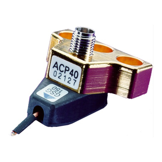
FormFactor ACP40-GSG Series Skrócona instrukcja obsługi - Strona 3
Przeglądaj online lub pobierz pdf Skrócona instrukcja obsługi dla Przyrządy pomiarowe FormFactor ACP40-GSG Series. FormFactor ACP40-GSG Series 4 stron. Probes

ACP40-GSG-xxx Probes
VNA Calibration and Verification
To achieve best measurement accuracy when doing microwave on-wafer measurements above 10-15 GHz, use LRRM
calibration routine with automatic load inductance determination as implemented in FormFactor WinCal software.
If you choose to do SOLT calibration, Calibration Kit Definitions for your probes are found on the inside of the probe box lid.
Use 1ps for the delay of the Thru standard on the ISS 101-190.
Some network analyzers do not support lumped inductance model and require offset Z
and offset T
. In this case, model your parasitic inductor for both Short and Load standards
d
as a short piece of transmission line. Assume the maximum impedance that the network
analyzer allows (typically 500 ohm) and calculate T
For example:
L = -1.7 pH
Z = 500 ohm
T
= -0.0034 ps
d
For verification of your calibration, measure S11 of an open standard and an open-ended transmission line located at the
bottom of the ISS (PN 101-190). Typical plots of such measurements with LRRM calibration are shown below.
Note that in the case of SOLT calibration the S11 of an Open standard will look perfect at 0dB (reflection coefficient of 1)
with variation due only to system repeatability; therefore, it is not a good choice for verification of your calibration accuracy.
Magnitude - S11 Open
Frequency range: 1.000-40.000 GHz, 40
101-190 GSG, Virtual VNA, Summit - Nucleus 2.7
09-07-2004 16:11:55 LRM open-load
PN 153-231-B
ACP-GSG 150 Probe Test
07-27-1998 15:55:16
C-open = -9.7 fF
L-short = 4.8 pH
S21 max = -0.67 dB
S11 min = -12.59 dB
using the following equation:
d
(GHz)
(GHz)
L-term = -1.70 pH
S22 min = -15.53 dB
Magnitude - S11 Open-Ended Transmission Line
www.formfactor.com
0
T
= L/Z
d
0
(GHz)
ACP40-GSG-xxx Probes • 3
