Dremel 231 Oryginalna instrukcja obsługi - Strona 5
Przeglądaj online lub pobierz pdf Oryginalna instrukcja obsługi dla Elektronarzędzie Dremel 231. Dremel 231 6 stron. Shaper/router table
Również dla Dremel 231: Instrukcja obsługi (8 strony), Podręcznik (16 strony)

• F ollow the dust-related national requirements for the materials
youņwantņtoņworkņwith.
• B e sure tool is switched off when plugging in.
DURING USE
• A lways keep the cord away from moving parts.
• N ever use the tool when cord or base-plate (=protective guard) is
damaged;ņhaveņitņreplacedņbyņaņqualifiedņperson.
• K eep hands and fingers away from router bit when tool is
switchedņon.
• I n case of electrical or mechanical malfunction, immediately
switchņoffņtheņtoolņandņdisconnectņtheņplug.
• I n case the router bit is blocked, resulting in jerking forces on the
tool,ņimmediatelyņswitchņoffņtheņtool.
• I n case of current interruption or when the plug is accidentally
pulledņout,ņimmediatelyņswitchņoffņtheņtoolņinņorderņtoņpreventņ
uncontrolledņrestarting.
• D o not apply so much pressure on the tool that it comes to a
standstill.
ENVIRONMENT
DISPOSAL
The machine, accessories and packaging should be sorted for
environmentalĶfriendlyņrecycling.
ONLY FOR EC COUNTRIES
Doņnotņdisposeņofņpowerņtoolsņintoņhouseholdņwaste!
AccordingņtheņEuropeanņGuidelineņ2002/96/ECņforņWasteņ
ElectricalņandņElectronicņEquipmentņandņitsņimplementationņ
intoņnationalņright,ņpowerņtoolsņthatņareņnoņlongerņusableņ
mustņbeņcollectedņseparatelyņandņdisposedņofņinņanņ
environmentallyņcorrectņmanner.
APPLICATION ADVICE
• U se the appropriate router bits.
• F or cuts parallel with the side of your workpiece use a rip fence.
• P rotect yourself against the effects of vibration by maintaining
theņtoolņandņitsņaccessories,ņkeepingņyourņhandsņwarm,ņandņ
organizingņyourņworkņpatterns.
ASSEMBLY
ATTACHMENT FOR USE WITH DREMEL ROTARY TOOL MODELS 300,
395, 398, 400, 4000.
ATTENTION:ņReadņentireņinstructionņmanualņcarefullyņbeforeņusingņyourņ
Dremel Shaper/Router Table. Retain instructions for future reference.
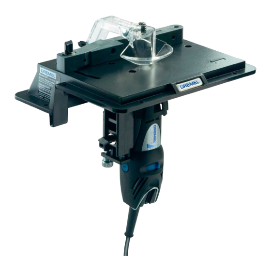
This attachment will convert Dremel Rotary Tools to a Shaper/Router
tableņforņedgeņforming,ņrouting,ņgrooving,ņshaping,ņsanding,ņedges,ņ
jointing,ņetc.
See Figure 1:
A
Base
B
CarriageņBolt
Tool Holder
C
D
LargeņKnob
E
DepthņAdjustmentņScrew
F
NutņĶņSquare
G
DepthņBracket
H
BracketņScrew
I
Pin
J
MountingņScrew
Thumb Nut
K
L
Guard
M
Sleeve
N
ClampņScrewņNut
O
Washerņ#9
P
Washerņ4,8ņmm
Fence
Q
R
WedgeņClampņScrew
S
Wedge
MOUNT TABLE TO WORKBENCH
The SHAPER/ROUTER TABLE comes assembled ready to mount on the
workbench.ņAfterņdeterminingņtableņlocation,ņpredrillņtheņbenchņusingņaņ
3,2ņmmņdiameterņdrillņatņtheņfourņmountingņholeņlocations.ņSecureņtableņ
toņtheņbenchņusingņtheņ4ņwoodņscrews,ņandņwashers.ņ(Includedņwithņtheņ
Shaper/Router Table.)
See Figure 2:
A
4ņWoodņScrewsņ&ņWashers
B
Useņ50ņmmņxņ100ņmmņasņalternativeņmountingņoption
INSTALL ROTARY TOOL TO TABLE
See Figure 3:
A
Guard
Fence
B
C
On/offņswitchņmustņfaceņforwardņsoņleftĶtoĶrightņmotionņwillņturnņ
toolņoff.
D
DepthņAdjustmentņScrew
E
ClampņKnob
1.ņ
Makeņsureņtheņpowerņcordņofņtheņrotaryņtoolņisņunpluggedņandņ
installņtheņrequiredņrouterņbit.
2.ņ
Loosenņtheņclampņknobņandņadjustņtheņheightņofņtheņtoolņholderņtoņ
theņlowestņposition.
3.ņ
Moveņtheņrotaryņtoolņfromņtheņundersideņinņtheņtoolņholderņandņ
turnņtheņnutņonņtopņofņtheņtoolņholderņtoņfixateņtheņrotaryņtool.ņUseņ
theņopenņendņspannerņtoņfastenņtheņnut.
OPERATING INSTRUCTIONS
CHANGING ROUTER BITS
1.ņ
Loosenņtheņclampņknobņandņadjustņtheņheightņofņtheņtoolņholderņtoņ
theņlowestņposition.
2.ņ
Rotateņtheņrotaryņtoolņsoņtheņshaftņlockņbuttonņcanņbeņoperatedņ
throughņanņopeningņinņtheņtoolņholder.
3.ņ
Applyņtheņshaftņlockņbuttonņandņloosenņtheņrouterņbit.
4.ņ
Removeņtheņrouterņbitņthroughņtheņtableņandņinstallņanotherņrouterņ
bit.
5.ņ
Applyņtheņshaftņlockņbuttonņandņfixateņtheņrouterņbit.
CUTTING DEPTH ADJUSTMENT
Loosenņtheņclampņknobņandņturnņtheņdepthņadjustmentņknobņtoņsetņ
cuttingņdepth.ņDepthņofņcutņwillņbeņtheņamountņtheņbitņextendsņaboveņ
theņshaper/routerņtable.
See Figure 4:
A
LargeņKnob
B
DepthņofņCut
Table
C
D
DepthņAdjustmentņScrew
Tool Holder Assembly
E
Adjustmentņmarkingsņonņtheņsideņofņtheņtoolņholderņfacingņoutwardņareņ
markedņinņinchesņandņmillimeters.ņViewņtheņmarkingsņpriorņtoņstartingņ
your project. Turn the depth adjustment knob to set desired depth. To
ensureņproperņsettings,ņroutņandņmeasureņcutņonņscrapņmaterial.
See Figure 5: Depth Adjustment Markings
A
Inchesņinņ1/8ņinchņincrements
B
Millimetersņinņ5ņmmņincrements
5
