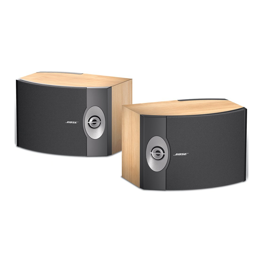
Bose 301 Series V Instrukcja obsługi - Strona 6
Przeglądaj online lub pobierz pdf Instrukcja obsługi dla System głośników Bose 301 Series V. Bose 301 Series V 12 stron. Direct/reflecting speakers
Również dla Bose 301 Series V: Instrukcja obsługi (13 strony), Instrukcja obsługi (12 strony), Instrukcja obsługi (21 strony), Instrukcja obsługi (13 strony), Instrukcja obsługi (16 strony), Podręcznik użytkownika (10 strony)

Setting Up
Choose the cord
It is important to use the proper gauge (thickness) of speaker cord. Standard zip cord
(2-conductor, 18-gauge wire) works for most applications. You can find this wire at most
electrical and hardware stores.
You will need thicker wire if your speakers will be more than 30 feet (9 m) from a receiver (or
amplifier). Refer to the wire recommendations under "Technical information" on page 10, or
contact your authorized Bose
Note: Before running speaker cord through a wall or under a floor, check your local
building code requirements and safety regulations. You may want to contact an electrical
installer for this information.
Prepare the cord
Speaker cord consists of two insulated wires. The insulation around one wire is marked
(striped, collared, or ribbed). This marked wire is always positive (+). The plain wire is always
negative (–). These wires correspond to the red (+) and black (–) terminals on the speakers
and the receiver.
At the ends of each cord, strip approximately
Twist the bare end of each wire so loose strands will not touch across terminals. Be sure to
connect each wire to the proper terminal (positive to positive and negative to negative).
Note: It is sometimes difficult to distinguish wire markings. Inspect both wires carefully.
Make the connections
Just press the terminal tab on the back of each speaker to insert the appropriate wire
(Figure 3).
1. Connect one speaker cord to your right speaker.
a. Attach the marked wire at one end to the red (+) terminal.
b. Attach the plain wire at that end to the black (–) terminal.
2. Connect the other end of the same cord to the RIGHT SPEAKER OUTPUT of your
receiver.
a. Attach the marked wire to the red (+) terminal.
b. Attach the plain wire to the black (–) terminal.
3. Connect the second cord to the left speaker and LEFT SPEAKER OUTPUT. Follow the
steps in 1 and 2 above.
Red terminal tab
Marked wire
6
®
dealer for more information.
1
⁄
inch (12 mm) of insulation from both wires.
2
+
—
+
—
October 30, 2001
CAUTION:
Never use broken or frayed
wiring, which can result in
electrical shock or damage.
CAUTION:
Before making any connec-
tions, turn off your receiver
and unplug it from the AC
power (mains) outlet. Not
doing so may result in dam-
age to your system.
Figure 3
How to make terminal connec-
tions
AM181869_04_V.pdf
