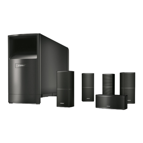
Bose Acoustimass 6 Instrukcja obsługi - Strona 10
Przeglądaj online lub pobierz pdf Instrukcja obsługi dla System głośników Bose Acoustimass 6. Bose Acoustimass 6 20 stron. Home entertainment speaker systems
Również dla Bose Acoustimass 6: Instrukcja obsługi (25 strony), Instrukcja obsługi (16 strony)

Setting Up
Connect the speakers
Note: You can refer to Figure 12 on page 12 for an overview of the completed connections.
The supplied cables make it easy for you to connect your system. Each cable connector is
colored gray or black and embossed with a letter to identify the cube speaker, the output, or
the input it matches. The connections at the Acoustimass
There are three sets of cables, joined together to form ribbons, which may be separated or
"unzipped" as needed to comfortably reach the speakers (Figure 9). Separate the cables as
you are laying out the cable lengths. However, you may want to keep the unextended length
of cable joined, making it easier to hide.
•
The 20 foot (6 m) cable with three pairs of wires connects the Acoustimass module to the
center, left front, and right front cube speakers.
•
The 50 foot (15 m) cable with two pairs of wires connects the Acoustimass module to the
left and right surround cube speakers.
•
The 20 foot (6 m) cable with five pairs of wires connects the Acoustimass module to the
outputs on the receiver. Separate these wires just enough to reach the connectors.
Note: If you have already installed cable behind walls or under floors, or believe you need
to splice the supplied cables for any other reason, inquire about the add-on connectors and
extension cable available from Bose
these accessories. Bose Customer Service telephone numbers are listed on the inside back
cover.
Connect the Acoustimass module to the center and front cube
speakers
Use the 20 foot (6 m) cable with three pairs of
wires to connect the Acoustimass module to
the center and front cube speakers. Just
press the custom connectors into place.
•
The gray connector goes into the gray
terminal on the center speaker (Figure 10).
•
The black connector marked L goes into
the black terminal on the left front speaker
(to the left of the TV as you face it).
•
The black connector marked R goes
into the black terminal on the right front
speaker.
10
®
module are already made for you.
®
Customer Service. Refer to page 17 for details on
December 20, 2001
L/R
C/S
L/R
CAUTION:
Before making any connec-
tions turn off your receiver or
amplifier and unplug it from
the outlet (AC power mains).
Not doing so may result in
damage to your system.
Figure 9
Separating cables
CAUTION:
Never use broken or frayed
wiring, which can result in
electrical shock or damage to
your system.
The supplied cables are not
intended for in-wall installa-
tion.
Figure 10
Inserting gray connector marked
C into the gray terminal marked
C/S
CAUTION:
Never connect the cubes
directly to the receiver. Always
connect the cube speakers to
the Acoustimass module, then
connect the Acoustimass
module to the receiver.
AM189815_04_V.pdf
