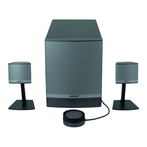
Bose Companion 3 Series II Instrukcja serwisowa - Strona 7

Przeglądaj online lub pobierz pdf Instrukcja serwisowa dla Wzmacniacz Bose Companion 3 Series II. Bose Companion 3 Series II 16 stron. Multimedia speaker system
Również dla Bose Companion 3 Series II: Instrukcja obsługi (40 strony), Instrukcja obsługi (40 strony), Instrukcja obsługi (22 strony), Instrukcja obsługi (10 strony), Instrukcja obsługi (20 strony), Instrukcja obsługi (26 strony), Podręcznik szybkiej konfiguracji (2 strony), Podręcznik szybkiej konfiguracji (2 strony), Szczegółowa instrukcja montażu (2 strony), Instrukcja instalacji (20 strony), Specyfikacje (6 strony), Broszura i specyfikacje (4 strony), Instrukcja obsługi (19 strony), Instrukcja serwisowa (36 strony)

Bose Companion 3 Series II Instrukcja serwisowa
Note: The input voltage should be the actual
voltage present at the input and not the open
circuit generator output.
1. Bass Module Air Leak Test
Note: Connect the system as shown in
figure 1, 6 Ohm mono test setup settings.
1.1 Apply a 6 Vrms, 50 Hz signal to the mono
input terminals of the bass module. Do not
connect the satellite speakers.
1.2 Listen carefully for air leaks from around
the terminal cup, port cap and cabinet
seams.
2. Woofer Phase Test
2.1 Apply a 6 Vrms, 50 Hz signal to both the
CH1 and CH2 stereo input terminals of the
bass module.
2.2 While the signal is being applied to the
bass module, remove the input to one of the
stereo terminals.
2.3 The sound output level should drop by
approximately half. If the sound output level
increases, stays the same, or stops com-
pletely, then there is a wiring problem at the
crossover PCB or woofer.
3. System Sweep Test
3.1 Connect the system as shown in figure
2, stereo test setup settings.
3.2 Apply a 6 Vrms, 10 Hz signal to the
stereo input terminals of the bass module.
3.3 While listening to the output of the sys-
tem, sweep the input frequency slowly from
10 Hz to 500 Hz. The output should cross
over from the bass module to the satellite
speakers.
Note: A whooshing noise from the bass
module port at around 40 Hz and 160 Hz to
180 Hz is acceptable.

TEST PROCEDURES

7
3.4 Reduce the input level to 3 Vrms.
3.5 Continue sweeping from 500 Hz to 15
kHz. Listen for a clean, undistorted output
from each satellite assembly. Replace any
satellite or woofer that buzzes or sounds
distorted.
4. 70/100 Volt Input Test Procedure
Note: This test is to ensure the transformer
is functioning. Connect the system as shown
in figure 4, 70/100V test setup settings.
4.1 Apply a 13 Vrms, 50 Hz signal to the bass
module at the 70 Volt input terminals.
4.2 Sweep the input frequency from 50 Hz to
500 Hz.
4.3 Apply a 13 Vrms, 50 Hz signal to the 100
Volt input terminals.
4.4 Sweep the input frequency from 50 Hz to
500 Hz.
Note: If the crossover or any components
on the crossover PCB are found to be
defective, replace the entire crossover PCB.