Bose Personalized Amplification System Instrukcja rozwiązywania problemów
Przeglądaj online lub pobierz pdf Instrukcja rozwiązywania problemów dla Wzmacniacz Bose Personalized Amplification System. Bose Personalized Amplification System 50 stron.
Również dla Bose Personalized Amplification System: Instrukcja obsługi (28 strony)
Contents .............................................................................................................................................1
Safety Information.............................................................................................................................2
Electrostatic Discharge Sensitive (ESDS) Device Handling .........................................................2
Theory of Operation ..........................................................................................................................3
Figure 1: PS1 signal flow Diagram ....................................................................................................3
Theory of Operation .................................................................................................................... 4-26
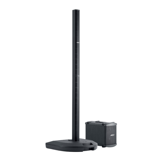
Figure 2. Personalized Amplification System
Figure 3. Powerstand Input and Output Connections .......................................................................5
Figure 4. R1 Remote Control ............................................................................................................5
Figure 5. DSP Functional Block Diagram .........................................................................................7
Figure 6. DC Power Supply Block Diagram ......................................................................................7
Table 1. Adjustable Controls: Gain range and nominal settings ......................................................12
Table 2. Nominal and Peak Signal Levels .......................................................................................13
Table 3. LED Trigger Levels ............................................................................................................14
Figure 7. Nominal Bass Configuration, 2 Bass Modules ................................................................14
Figure 8. Light Bass configuration ..................................................................................................15
Figure 9. External power stand, total of 4 bass modules ................................................................15
Figure 10. "Heavy" Bass, total of 8 bass modules ..........................................................................16
Table 4. Ideal and actual bass EQ gains .........................................................................................16
Table 5. EQ lookup table for all operational modes.........................................................................17
Table 6. Peripheral pins on the microcontroller ...............................................................................22
Figure 11. PS1 Tone Control Range ...............................................................................................24
Test Procedures ........................................................................................................................ 27-31
PS1 Power Stand Tests ...................................................................................................................27
Line Array Tests ...............................................................................................................................30
Bass Module Tests ..........................................................................................................................31
Appendix .................................................................................................................................... 32-48
PS1 Power Stand Software Update Procedure ............................................................................32
PS1 Power Stand Test Cables .................................................................................................. 33-34
1. Amplifier Output Test Cable .......................................................................................................33
2. XLR Microphone Input Test Cable .............................................................................................34
3. Line Input 1/4" Phono Jack Test Cable ......................................................................................34
4. Insert Jack Test Cable .................................................................................................................34
5. L1 Line Array Test Cables ...........................................................................................................35
6. Bass Module Test Cable .............................................................................................................35
IC Diagrams ............................................................................................................................... 36-48
CAUTION: The Bose
no user-serviceable parts. To prevent warranty infractions,
refer servicing to warranty service stations or factory service.
THIS DOCUMENT CONTAINS PROPRIETARY INFORMATION OF
BOSE CORPORATION WHICH IS BEING FURNISHED ONLY FOR
THE PURPOSE OF SERVICING THE IDENTIFIED BOSE PRODUCT
BY AN AUTHORIZED BOSE SERVICE CENTER OR OWNER OF
THE BOSE PRODUCT, AND SHALL NOT BE REPRODUCED OR
USED FOR ANY OTHER PURPOSE.
CONTENTS
Components ...........................................................4
®
PROPRIETARY INFORMATION
1
TM
contains