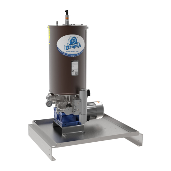
DROPSA 2451011 Instrukcja obsługi i konserwacji - Strona 5
Przeglądaj online lub pobierz pdf Instrukcja obsługi i konserwacji dla Pompa wodna DROPSA 2451011. DROPSA 2451011 13 stron.

5.1.1 INVERTERS
For technical characteristics and procedures for use of inverters use the product-specific manual attached to the pump.
5.1.2 POMPANTI A PORTATA FISSA
The pump is set with one or two fixed flow rate pumping elements (190 cm^3/ min for each pumping element).
The sealing between piston and pumping body is of dry type, not being provided any gasket in between.
Pumping check valve is tapered seal type. This solution ensures excellent tightness of the system at high operating pressures
(max pressure 400 bar – 5800psi).
Pumping elements are fitted on the pump body without need to disconnect piping of the line with a threaded connection which
gives an easy assembly / disassembly.
5.1.2
MAXIMUM AND MINIMUM LEVEL FOR OIL AND GREASE
5.1.3.1
Minimum laser level for grease
When the lubricant reaches minimum level, the laser probe signals the lack of lubricant. The probe has two outputs, the first NO
and the second NC when lubricant is present.
For connections and calibration see paragraph7.3.1 and 7.3.2.
5.1.3.2
Maximum/ Minimum floating level for oil
A probe rod with dual float mounted on the pump cover provides a reading of the minimum oil level (reserve) and the maximum
level (which allows the automatic refilling of the tank to be halted).
For connections see paragraph 7.3.4.
5.1.3.3
visual floating level for oil/grease
Maximum
The phase that the lubricant is loaded in the tank is realised by the operator, who uses a pump.
Once the maximum lubricant level is reached, a rod is activated that indicates that the tank is full.
5.2
ELECTRICAL CONTROL PANEL
"DROPSA" electrical control panel has been designed to provide a system complete with all the controls necessary for automatic
functioning controlled by safety signals from centralized lubrication installations. The primary voltage is 400 VAC and 50 Hz, the
other voltages are on request.
TYPE OF
TYPE OF PROBE
INVERTER*
LASER PROBE or
Electromagnetic or
FLOATING
hydraulic valve
(24V cc standard
version)
4/2 Electro
Out NO e NC
pneumatic
(1 threshold)
hydraulic valve
LASER PROBE or
Electromagnetic
FLOATING
hydraulic valve
24V cc Out
4/2 Electro
4÷20mA/2 NO
pneumatic
(4 thresholds)
hydraulic valve
* For control equipment with 4/3 inverters contact the Dropsa Technical Sales.
** Contact the sales office Dropsa for other primary and the inverter supply voltages
VOLTAGE
CODE ELECTRICAL
V**
APPARATUS VIP5 PRO
4/2
24 VDC
4/2
24 VDC
CODE ELECTRICAL APPARATUS
1639211
VIP5 PLUS
APPARATUS WITH PLC
1639210
CODE ELECTRICAL
1637008
1637011
1637001
1637005
