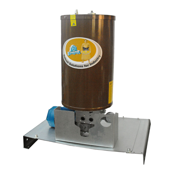
DROPSA 2487061 Instrukcja obsługi i konserwacji dla użytkownika - Strona 7
Przeglądaj online lub pobierz pdf Instrukcja obsługi i konserwacji dla użytkownika dla Pompa wodna DROPSA 2487061. DROPSA 2487061 18 stron.

5.1.2 MINIMUM AND MAXIMUM GREASE LEVEL INDICATORS
The standard grease pumps have two level types:
• Minimum laser level (for 10 and 30 Kg reservoir);
• Max visible level (floating).
5.1.3 Minimum laser level
The minimum level is realised by a laser probe. When the lubricant reaches minimum level, the laser probe signals the lack of
lubricant. The probe has two outputs, the first NO and the second NC when lubricant is present. When the minimum level is
reached, the probe signals that the lubricant is low.
The minimum level contact is indicated by a light signal on the electric panel. In addition the panel controls any automatic
reservoir filling pump command.
5.1.4 Max visible level (floating)
The phase that the lubricant is loaded in the tank is realised by the operator, who uses a pump.
Once the maximum lubricant level is reached, a rod is activated that indicates that the tank is full.
5.1.5 MINIMUM AND MAXIMUM OIL LEVEL INDICATORS
The standard oil pumps have two level types:
• Minimum and maximum level with a float;
• Max visible level (floating).
5.1.6 Minimum and maximum level with a float
A rod probe with a dual float mounted on the pump cover makes it possible to read the minimum oil level (reserve) and the
maximum level (which makes it possible to stop automatic tank filling).
The minimum level contact is indicated by a luminous signal on the electric panel, it also controls any automatic tank filling
pump command.
5.1.7 SPATULA FOR GREASE AND OIL (STANDARD VERSION)
Two tanks have been foreseen with capacities of 10 and 30 kg. (22 – 66.1 Lb) two for oil and two for grease.
The tanks are supplied standard with a spatula and a scraper, which must not be disassembled during their assembly or
replacement. Under the spatula, there is a standard electrogalvanised steel mesh with 0.5 mm holes (0.02 in.). The pump is
protected from possible foreign bodies that could be inadvertently present while the tank is being loaded.
5.2. OPTIONAL PUMP COMPONENTS
5.2.1 Interchangeable electromagnetic change-over
An electromagnetically controlled inverter is available for dual line operation. The inverter can be replaced in the case of
damage without having to disconnect the two line pipes (interchangeable version). This reduces the maintenance time and the
time the plant is stopped.
The main change-over parts are:
• a casing with a central lapped hole that makes it possible
to make a dry seal connection with the inversion piston,
which is facilitated by a balancing system;
• a ground piston with a dual coupling surface, with grooves
that improve lubrication and the seal at high pressures;
• sealing gaskets that can support high pressure levels, by
means of a pressurised chamber, optimising the inverter
function;
• Two control electro-magnets
Advantages:
• easy to assemble and disassemble without disconnecting
the line tubes
• Minimum time the plant is stopped.
7
