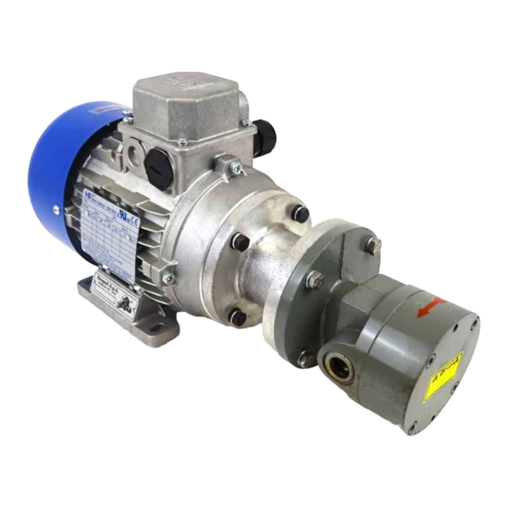
DROPSA 37056 Instrukcja obsługi i konserwacji - Strona 8
Przeglądaj online lub pobierz pdf Instrukcja obsługi i konserwacji dla Pompa wodna DROPSA 37056. DROPSA 37056 16 stron. Motor driven gear pumps

This assembly consists only of the motor and the gear pump.
DropsA
By-pass
Line
setting
01
2-20 bar
26
25-80 bar
33V
25-80 bar
This assembly is composed of a gear pump, an electric motor, a manometer and a valve block.
Thanks to a by-pass it is possible to regulate the working pressure in accordance with the requirements of the system to which
the pump is connected.
Also included in the valve block is a non-return valve or alternatively a release valve so that it can be adapted for use with the
different DROPSA systems (line 01, line 26, 33V System) or on other systems of a similar nature.
It is also possible to order separately an intake filter with a dip tube (400 mesh/cm2 filtering grade 260) of an overall length
variable between 100 and 455 mm depending on the differing requirements of the installation).
THE MOTOR VOLTAGE MUST ALWAYS BE STATED AT THE TIME OF ORDERING.
Standard
By-pass
Assembly
setting
3404023
3404022
5 bar
with
non-
3404026
return
3404046
valve
3405099
3405101
70 bar/
3 PH
3405121
3415122
with
3405098
release
3405100
50 bar/
valve
3 PH
3405123
3405124
Motor power
Size
kW
rpm
56
0.09
1500
220/380V-50 Hz
56
0.09
1500
220/380V-50 Hz
56
0.06
1500
110 V – 50 Hz
56
0.06
1500
110 V – 50 Hz
56
0.09
1500
220/380V – 50 Hz
56
0.09
1500
220/380V– 50 Hz
56
0.06
1500
110 V – 50 Hz
56
0.06
1500
110V – 50 Hz
56
0.12
1500
220/380V-50 Hz
56
0.12
1500
220/380V-50 Hz
56
0.06
1500
110 V – 50 Hz
56
0.06
1500
110 V – 50 Hz
Voltage
Flow
rate
*A
litres/mi
n
0.35
205 156 110
0.50
205 156 110
0.35
205 156 110
0.50
205 156 110
0.35
205 156 110
0.50
205 156 110
0.35
205 156 110
0.50
205 156 110
0.35
187 156 110
0.50
187 156 110
0.35
205 156 110
0.50
205 156 110
* NON-STANDARD DIMENSIONS
Dimensions
*B
*C
D
38
40
38
40
38
40
38
40
38
40
38
40
8
