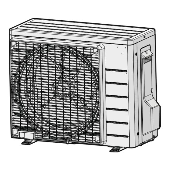
Daikin R32 Split Series Instrukcja instalacji - Strona 12
Przeglądaj online lub pobierz pdf Instrukcja instalacji dla Wentylator Daikin R32 Split Series. Daikin R32 Split Series 17 stron. R32 split series
Również dla Daikin R32 Split Series: Instrukcja instalacji (16 strony), Instrukcja instalacji (16 strony), Instrukcja instalacji (16 strony), Instrukcja instalacji (17 strony), Instrukcja instalacji (16 strony), Instrukcja instalacji (20 strony), Instrukcja instalacji (14 strony), Instrukcja instalacji (14 strony), Instrukcja obsługi (16 strony), Instrukcja obsługi (16 strony), Instrukcja obsługi (8 strony), Instrukcja instalacji (17 strony), Instrukcja instalacji (16 strony), Instrukcja instalacji (20 strony), Instrukcja instalacji (20 strony), Instrukcja instalacji (16 strony), Instrukcja instalacji (16 strony), Instrukcja instalacji (14 strony), Instrukcja instalacji (14 strony), Instrukcja instalacji (16 strony), Instrukcja instalacji (17 strony), Instrukcja instalacji (20 strony), Instrukcja instalacji (13 strony)

- 1. Installation Manual
- 2. Safety Precautions
- 3. Choosing an Installation Site
- 4. Indoor Unit
- 5. Wireless Remote Controller
- 6. Preparation before Installation
- 7. Indoor Unit Installation Drawings
- 8. Indoor Unit Installation
- 9. Installing the Indoor Unit
- 10. Wiring Diagram
- 11. Refrigerant Piping Work
- 12. Drain Piping
- 13. Refrigerant Piping
- 14. Trial Operation and Testing
