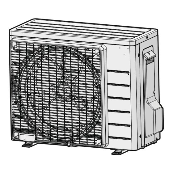
1. CHECKLIST BEFORE COMMISSIONING
1. CHECKLIST BEFORE COMMISSIONING
Do NOT operate the system before the following checks are OK:
Do NOT operate the system before the following checks are OK:
The indoor unit is properly mounted.
The indoor unit is properly mounted.
The outdoor unit is properly mounted.
The outdoor unit is properly mounted.
The system is properly earthed and the earth terminals are tightened.
The system is properly earthed and the earth terminals are tightened.
The fuses or locally installed protection devices are installed according to this document, and have NOT been
The fuses or locally installed protection devices are installed according to this document, and have NOT been
bypassed.
bypassed.
The power supply voltage matches the voltage on the identification label of the unit.
The power supply voltage matches the voltage on the identification label of the unit.
There are NO loose connections or damaged electrical components in the switch box.
There are NO loose connections or damaged electrical components in the switch box.
There are NO damaged components or squeezed pipes on the inside of the indoor and outdoor units.
There are NO damaged components or squeezed pipes on the inside of the indoor and outdoor units.
There are NO refrigerant leaks.
There are NO refrigerant leaks.
The refrigerant pipes (gas and liquid) are thermally insulated.
The refrigerant pipes (gas and liquid) are thermally insulated.
The correct pipe size is installed and the pipes are properly insulated.
The correct pipe size is installed and the pipes are properly insulated.
The stop valves (gas and liquid) on the outdoor unit are fully open.
The stop valves (gas and liquid) on the outdoor unit are fully open.
The following field wiring has been carried out according to this document and the applicable legislation
The following field wiring has been carried out according to this document and the applicable legislation
between the outdoor unit and the indoor unit.
between the outdoor unit and the indoor unit.
Drainage
Drainage
Make sure drainage flows smoothly.
Make sure drainage flows smoothly.
Possible consequence: Condensate water might drip.
Possible consequence: Condensate water might drip.
The indoor unit receives the signals of the user interface.
The indoor unit receives the signals of the user interface.
The specified wires are used for the interconnection cable.
The specified wires are used for the interconnection cable.
2. CHECKLIST DURING COMMISSIONING
2. CHECKLIST DURING COMMISSIONING
To perform an air purge.
To perform an air purge.
To perform a test run.
To perform a test run.
IR Signal Receiver
IR Signal Receiver
When an infrared remote control operating signal has
When an infrared remote control operating signal has
been transmitted, the signal receiver on the indoor unit
been transmitted, the signal receiver on the indoor unit
will respond as below to confirm acceptance of the signal
will respond as below to confirm acceptance of the signal
transmission.
transmission.
ON to OFF
ON to OFF
OFF to ON
OFF to ON
Pump down/Cool force on
Pump down/Cool force on
Others
Others
Heatpump Unit
Heatpump Unit
The table shows the LED indicator lights for the air
The table shows the LED indicator lights for the air
conditioner unit under normal operation and fault
conditioner unit under normal operation and fault
conditions. The LED indicator lights are located at the
conditions. The LED indicator lights are located at the
side of the air conditioner unit.
side of the air conditioner unit.
The heat pump units are equipped with an "auto"
The heat pump units are equipped with an "auto"
mode sensor whereby it will provide reasonable room
mode sensor whereby it will provide reasonable room
temperature by switching automatically to either "cool" or
temperature by switching automatically to either "cool" or
"heat" mode according to the temperature set by the user.
"heat" mode according to the temperature set by the user.
COMMISSIONING
COMMISSIONING
INDICATION LIGHTS
INDICATION LIGHTS
1 Long Beep
1 Long Beep
2 Short Beep
2 Short Beep
1 Short Beep
1 Short Beep
LED INDICATOR LIGHTS
LED INDICATOR LIGHTS
LED Indicator Lights for Heatpump Unit
LED Indicator Lights for Heatpump Unit
ENGLISH
ENGLISH
IR RECEIVER
IR RECEIVER
ON/OFF DISPLAY
ON/OFF DISPLAY
TIMER
TIMER
ON/OFF SWITCH
ON/OFF SWITCH
15
15

