Daikin R32 Split Series Instrukcja instalacji - Strona 13

Przeglądaj online lub pobierz pdf Instrukcja instalacji dla Wentylator Daikin R32 Split Series. Daikin R32 Split Series 16 stron. R32 split series
Również dla Daikin R32 Split Series: Instrukcja instalacji (17 strony), Instrukcja instalacji (16 strony), Instrukcja instalacji (16 strony), Instrukcja instalacji (16 strony), Instrukcja instalacji (17 strony), Instrukcja instalacji (16 strony), Instrukcja instalacji (20 strony), Instrukcja instalacji (14 strony), Instrukcja instalacji (14 strony), Instrukcja obsługi (16 strony), Instrukcja obsługi (16 strony), Instrukcja obsługi (8 strony), Instrukcja instalacji (17 strony), Instrukcja instalacji (16 strony), Instrukcja instalacji (20 strony), Instrukcja instalacji (20 strony), Instrukcja instalacji (16 strony), Instrukcja instalacji (14 strony), Instrukcja instalacji (14 strony), Instrukcja instalacji (16 strony), Instrukcja instalacji (17 strony), Instrukcja instalacji (20 strony), Instrukcja instalacji (13 strony)
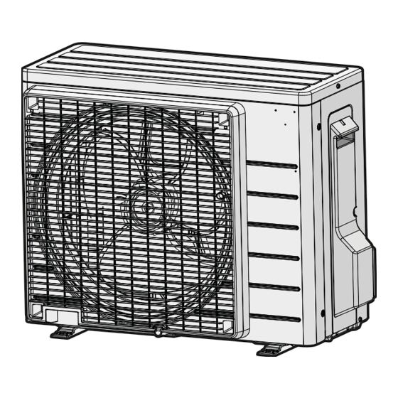
Daikin R32 Split Series Instrukcja instalacji
3 Turn ON the main power supply.
10

Commissioning

NOTICE
General
commissioning
commissioning instructions in this chapter, a general
commissioning checklist is also available on the Daikin
Business Portal (authentication required).
The general commissioning checklist is complementary to
the instructions in this chapter and can be used as a
guideline and reporting template during commissioning and
hand-over to the user.
NOTICE
ALWAYS operate the unit with thermistors and/or pressure
sensors/switches. If NOT, burning of the compressor might
be the result.
10.1

Checklist before commissioning

1 After the installation of the unit, check the items listed below.
2 Close the unit.
3 Power up the unit.
The indoor unit is properly mounted.
The outdoor unit is properly mounted.
The system is properly earthed and the earth terminals
are tightened.
The power supply voltage matches the voltage on the
identification label of the unit.
There are NO loose connections or damaged electrical
components in the switch box.
There are NO damaged components or squeezed
pipes on the inside of the indoor and outdoor units.
There are NO refrigerant leaks.
The refrigerant pipes (gas and liquid) are thermally
insulated.
The correct pipe size is installed and the pipes are
properly insulated.
The stop valves (gas and liquid) on the outdoor unit are
fully open.
The following field wiring has been carried out according
to this document and the applicable legislation between
the outdoor unit and the indoor unit.
Drainage
Make sure drainage flows smoothly.
Possible consequence: Condensate water might drip.
ARXD25+35A5V1B
R32 Split series
3P650253-15Q – 2022.12
checklist.
Next
to
the
The indoor unit receives the signals of the user interface.
The specified wires are used for the interconnection
cable.
The fuses, circuit breakers, or locally installed protection
devices are installed according to this document, and
have NOT been bypassed.
10.2

Checklist during commissioning

To perform an air purge.

To perform a test run.

10.3
To perform a test run
Prerequisite: Power supply MUST be in the specified range.
Prerequisite: Test run may be performed in cooling or heating
mode.
Prerequisite: Test run should be performed in accordance with the
operation manual of the indoor unit to make sure that all functions
and parts are working properly.
1 In cooling mode, select the lowest programmable temperature.
In heating mode, select the highest programmable temperature.
Test run can be disabled if necessary.
2 When the test run is finished, set the temperature to a normal
level. In cooling mode: 26~28°C, in heating mode: 20~24°C.
3 The system stops operating 3  minutes after the unit is turned
OFF.
INFORMATION
▪ Even if the unit is turned OFF, it consumes electricity.
▪ When the power turns back on after a power break, the
previously selected mode will be resumed.
11

Troubleshooting

11.1
Fault diagnosis using LED on
outdoor unit PCB
LED is...
Diagnosis
flashing
Normal.
▪ Check the indoor unit.
ON
▪ Turn the power OFF and back ON, and
check the LED within approximately 3
minutes.
If the LED is ON again, the outdoor unit
PCB is faulty.
OFF
1
Supply voltage (for power saving).
2
Power supply fault.
3
Turn the power OFF and back ON, and
check the LED within approximately 3
minutes.
If the LED is OFF again, the outdoor unit
PCB is faulty.
DANGER: RISK OF ELECTROCUTION
▪ When the unit is NOT operating, the LEDs on the PCB
are turned OFF in order to save power.
▪ Even when the LEDs are OFF, the terminal block and
the PCB may be powered.
10 Commissioning
Installation manual
13