Daikin R32 Split Series Instrukcja instalacji - Strona 12

Przeglądaj online lub pobierz pdf Instrukcja instalacji dla Wentylator Daikin R32 Split Series. Daikin R32 Split Series 16 stron. R32 split series
Również dla Daikin R32 Split Series: Instrukcja instalacji (17 strony), Instrukcja instalacji (16 strony), Instrukcja instalacji (16 strony), Instrukcja instalacji (16 strony), Instrukcja instalacji (17 strony), Instrukcja instalacji (16 strony), Instrukcja instalacji (20 strony), Instrukcja instalacji (14 strony), Instrukcja instalacji (14 strony), Instrukcja obsługi (16 strony), Instrukcja obsługi (16 strony), Instrukcja obsługi (8 strony), Instrukcja instalacji (17 strony), Instrukcja instalacji (16 strony), Instrukcja instalacji (20 strony), Instrukcja instalacji (20 strony), Instrukcja instalacji (16 strony), Instrukcja instalacji (16 strony), Instrukcja instalacji (14 strony), Instrukcja instalacji (14 strony), Instrukcja instalacji (17 strony), Instrukcja instalacji (20 strony), Instrukcja instalacji (13 strony)
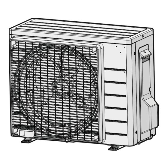
Daikin R32 Split Series Instrukcja instalacji

Installation Tips

1.

Removing and installing the front panel

• Removal method
1) Place your fingers in the indentations on the main unit (one each on the left and right sides), and open the front panel
until it stops.
2) While pushing the left side front panel shaft outward, push up the
front panel and remove it.
(Remove the right side front panel shaft in the same manner.)
3) After removing both front panel shafts, pull the front panel toward
yourself and remove it.
• Installation method
Align the front panel shaft of the front panel with the grooves of grille, and push all the way in, then close slowly.
Push the center of the lower panel surface firmly to engage the tabs.
2.

Removing and installing the front grille

• Removal method
1) Remove the front panel and air filters.
2) Remove the lower flap. (See Fig.1)
(Do not remove the upper flap.)
3) Remove screw covers (2 pcs.)*. (See Fig.2)
*The 18/24 class models have 3 screw covers.
4) Remove the front grille fixing screws (3 screws)*. (See Fig.2)
*The 18/24 class models have 5 screws.
5) Remove the service lid screws (1 screw) and remove service lid.
(See Fig.3)
6) In front of the
hooks. Lightly pull the front grille toward you with one hand,
and push down on the hooks with the fingers of your other
hand. (See Fig.4)
When there is insufficient work space because the
unit is close to ceiling
Place both hands under the center of the front grille, and while pushing up, pull it toward
you.
• Installation method
1) Install the front grille and firmly engage the upper hooks (3 locations).
2) Install the 3 screws*
*1 The 18/24 class models have 5 screws.
*2 The 18/24 class models have 3 screw covers.
3) Install the service lid and screw for fixing the service lid (1 screw).
4) Install the air filters and then mount the front panel.
3.

How to set the different addresses

When 2 indoor units are installed in one room, the 2 wireless remote controllers can be set for different addresses. Change the
address setting of one of the 2 units. When cutting the jumper, be careful not to damage any of the surrounding parts.
1) Remove the battery cover on the remote controller and cut the address jumper (J4).
2) Press
,
3) Press
, select
(The indoor unit OPERATION lamp will blink for about 1 minute.)
4) Press the indoor unit ON/OFF switch while the OPERATION lamp is blinking.
• If setting could not be carried out completely while the OPERATION lamp
was blinking, carry out the setting process once again from the beginning.
• After setting is complete, pressing
the remote controller to return to the previous display.
11
mark on the front grille, there are 3 upper
1
of the front grille and screw covers (2 pcs.)*
and
at the same time.
, press
.
for about 5 seconds will cause
Front panel
shaft
Upper flap
One each on the
left and right sides
Lower flap
Fig.1
Screw M4 × 1/2"
(M4 × 12mm)
Fig.3
2
.
Jumper (J4)
Jumper J4
Indoor unit
ON/OFF switch
Push the front panel
shaft of the front panel
into the groove.
Screw cover
Long flat plate
wrapped in a cloth
Fig.2
Service
lid
Fig.4
1) Push up.
2) Pull toward
you.
CAUTION
• Be sure to wear
protection gloves.
Address
1
2
EXIST
CUT
English