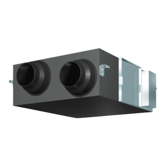
Daikin VAM800HVE Instrukcja obsługi - Strona 10
Przeglądaj online lub pobierz pdf Instrukcja obsługi dla Wentylator Daikin VAM800HVE. Daikin VAM800HVE 20 stron. Total heat exchanger, heat reclaim ventilator

• Use electric insulation between the duct and
the wall when using metal ducts to pass metal
or wire laths or metal plating into wooden
buildings.
This may cause electric shock, short circuits, or fire.
• Avoid placing the controller in a spot splashed
with water.
Water coming inside the controller may cause an
electric leak or may damage the internal electronic
parts.
• Never pull or twist the electric wire of a remote
controller.
It may cause the unit to malfunction.
(For moving and
WARNING
reinstalling/repairing)
• Do not modify the unit.
This may cause electric shock or fire.
• Ask your dealer to move and reinstall the unit.
Incomplete installation may result in electric shock,
and fire.
• Do not disassemble or repair the unit yourself.
This may cause electric shock or fire.
Contact your dealer to have such work done.
• When removing the unit, be sure not to tip it.
The water inside the unit may drip or leak out, and
get on furniture, etc.
• Do not move or attempt to re-install the remote
controller yourself.
Incorrect installation, may cause electric shock or
fire. Contact your dealer to have such work done.
2 WHAT TO DO BEFORE OPERATION
This operation manual is for the following systems with
standard control. Before initiating operation, contact
your Daikin dealer for the operation that corresponds
to your system type and mark.
If your installation has a customized control system,
ask your dealer for the operation that corresponds to
your system.
2-1 NAMES OF PARTS (Refer to figure 1)
(1) Lifting lug
(2) Duct connecting fl ange
(3) Exhaust fan
(4) Air fi lter (Long life fi lter)
(5) Damper
(6) Electric parts box
(7) Maintenance cover
(8) Heat exchanger elements
(9) Name plate
(10) Air supply fan
(11) Remote controller (Optional accessory)
(12) Damper motor
(13) EA Exhaust air to outdoors
(14) OA Fresh air from outdoors
(15) Maintenance space for the air fi lters, the heat
exchange elements and control box.
(16) RA Return air from room
(17) SA Supply air to room
3
2-2 VENTILATION OPERATION
See the operation manual of the remote control for
operations.
<Operating Conditions>
To ensure the correct usage of the unit, operate it
within the operating conditions specified in the table
below.
Surrounding
of total heat
exchanger
unit
-10°C to
VAM-HVE
50°CDB
Max. 80%RH
* If the unit is operated for long periods of time out of
temperature or operational humidity range, safety
devices may cause the unit to not operate, and water
may leak from the unit due to dew condensation.
2-3 OPTIMUM OPERATION
• Do not operate the unit in Bypass mode when
the room air is heated in winter or when the
outside temperature is 25°C or higher.
This may cause condensation to form on the main
unit or on the indoor air outlet.
• Do not install the remote control where the
indoor temperature and humidity, respectively,
is out of the range of 0-35°C and RH 40-80%.
This may cause malfunction.
• Do not change operations suddenly.
It can result not only in malfunction but also failure
of switches and relays in the remote control.
• Clean the air filter frequently.
If the unit is used with a clogged air filter, it may
lead to lower operation efficiency and failure.
Refer to Page 6 and 7
• Keep the indoor unit and the remote control at
least 1 m away from televisions, radios, stereos,
and other similar equipment.
This may cause distorted picture or noise.
• Turn off the main power supply when it is not
used for long periods of time.
When the main power switch is turned on, some
watts of electricity is being consumed even if the
system is not operating.
• Do not install the remote controller where direct
sunlight may fall on it.
This may cause discoloration or deformation.
Supplied
Exhausted
(outdoor) air
(indoor) air
-15°C to
-10°C to
50°CDB
50°CDB
Max.
Max.
80%RH
80%RH
