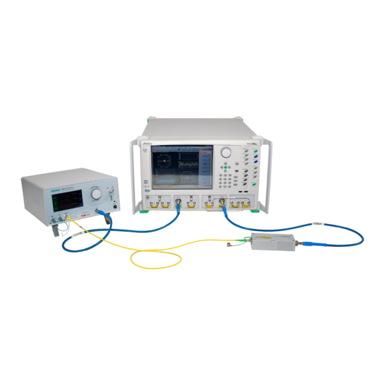
Anritsu Company VectorStar ME7848A-0170 Skrócona instrukcja obsługi - Strona 11
Przeglądaj online lub pobierz pdf Skrócona instrukcja obsługi dla Przyrządy pomiarowe Anritsu Company VectorStar ME7848A-0170. Anritsu Company VectorStar ME7848A-0170 17 stron. Opto-electronic network analyzer systems
Również dla Anritsu Company VectorStar ME7848A-0170: Skrócona instrukcja obsługi (15 strony)

Functional Test
1. Measurement setup
a. Set the VNA to sweep from 70 kHz to the 40/70/110 GHz (depending on the system), 201 points,
100 Hz IFBW, +5 dBm for -0240 systems and -10 dBm for the -021x/-027x systems.
b. Set the display parameter to be user-defined b2/1|P1.
c. Connect an RF thru line (ends of RF cables connected together).
d. Perform a port 2 test receiver calibration (under the power menu). The plot after the cal should be
a flat line at -10 dB.
2. Connect the port 1 RF cable to the modulator input and the port 2 RF cable to the O/E calibration module
as before (VNA/module ports can be used directly as well in many cases). Also ensure the optical patch
cord is in place. Activate the laser and set the modulator as discussed in the previous section.
3. The response is the absolute detected power and will have a similar shape to the |S21| plots in the
previous section but the numerical levels will be different.
Figure 3.
Example Plot of the Functional Test at +5 and +2 dBm Optical Power Levels
An example plot of the functional test is shown in
power (blue curve) and +2 dBm optical power (for reference, red curve). The -0271/0272 and -0240 systems will
have values somewhat lower than the red curve (2-5 dB for the -0271/0272 and 5-10 dB lower for the -0240).
110 GHz systems will have similar curves.
ME7848A/E QSG
Figure 3
for the ME7848A-0270 system at +5 dBm optical
PN: 10410-00777 Rev. C
3. System Check
QSG-11
