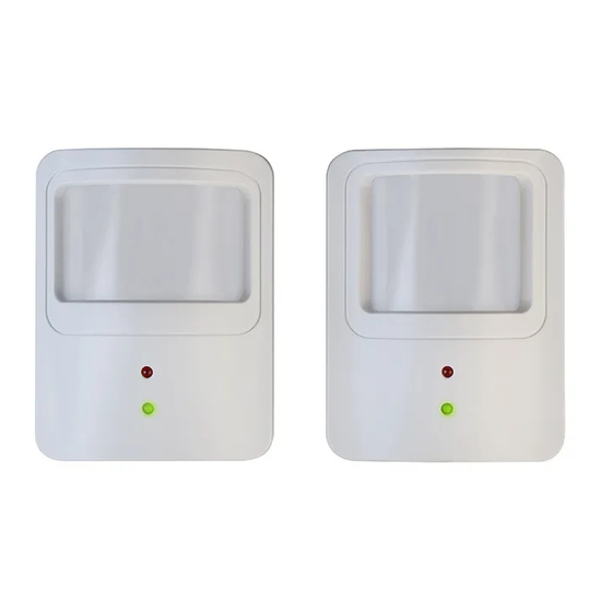
Daintree Networks WOS2-WM Instrukcja instalacji
Przeglądaj online lub pobierz pdf Instrukcja instalacji dla System bezpieczeństwa Daintree Networks WOS2-WM. Daintree Networks WOS2-WM 4 stron. Wireless occupancy sensor (wall mount) with photosensor

WOS2-WM
Wireless Occupancy Sensor (Wall Mount)
with Photosensor
Installa on Instruc ons
The Daintree Networks wall mounted Wireless Occupancy
Sensor (WOS2-WM) operates seamlessly within the
ControlScope™ wireless ligh ng control pla orm. The
WOS2-WM is a ba ery-powered occupancy sensor u lizing
passive infrared (PIR) sensing technology to detect movement.
As part of the ControlScope system and using open, standards
based ZigBee wireless communica ons, the WOS2-WM reports
real- me occupancy events to turn on lights or keep them on
when movement is detected, and turn off lights when a space is
vacant. The sensor's off -delay mer is user-confi gurable from any
loca on using the ControlScope Manager (CSM) web applica on,
elimina ng the need for on-site, manual sensor adjustment.
The WOS2-WM also includes a photosensor that can op onally
be confi gured with a daylight hold-off threshold to keep lights off
when a space is adequately lit by natural light.
Specifi ca ons
Power Supply
(2) Lithium-thionyl chloride ba eries
(Li-SOCl2) AA 3.6V (included)
Ba ery Life
5 years (normal opera on)
Radio Proper es
2.4 GHz, +7dBm transmit power
Sensor Coverage
110°, 11 m/36 (WOS2-WM-W)
(maximum)
20°, 30 m/98 (WOS2-WM-L)
Off -Delay Timer
30 seconds (fi xed), addi onal delay me
confi gurable in CSM
Photosensor
1 to 2000 Lux (0.093 to 185.8 fc)
Opera ng
14°F to +122°F (-10°C to 50°C)
Environment:
Indoor use only
Compliance
FCC Part 15B, FCC ID: NRH-ZB-Z100B
ICES/NMB-003 Class B, IC: 8984A-Z100B
Moun ng:
(2) Screw holes on swivel mount bracket;
wall (or ceiling) mount
Dimensions:
3.6" W x 2.8" H x 3" D
(92mm W x 70mm H x 77mm D)
Weight (without ba ery): 3.32 oz. (94g)
©2012 Daintree Networks, Inc.
Installa on Process
• Keep the sensor lens clean. Avoid touching the sensor lens.
• A er fi rst- me installa on or reinstalla on of a new ba ery,
allow up to three minutes for ini aliza on.
1. Determine the moun ng loca on for the sensor based on
the desired occupancy coverage.
See
Placement
2. A ach the moun ng base to the wall
in the specifi ed loca on.
3. Record the sensor's IEEE address and
loca on on the facility fl oor plan.
4. Install the ba eries in the orienta on
(+ - ) shown on the bo om of the ba ery
compartment.
5. A ach the sensor's main unit to the ball socket on the
moun ng base. Adjust the angle of the sensor, then
hand- ghten the collar to secure the angle.
www.daintree.net
Infrared
Detec on &
Test Mode LED
(red)
Network LED
(green)
for details.
Counter-clockwise to
Loosen or Remove
Clockwise to
Tighten
WOS2-WM 120731
