Atten AT5000 Instrukcja obsługi - Strona 11
Przeglądaj online lub pobierz pdf Instrukcja obsługi dla Przyrządy pomiarowe Atten AT5000. Atten AT5000 20 stron. Spectrum analyzers

station are instability, normally between -70dBm to
90dBm, and maybe weaker in some place or even
no signal. In order to make it easier to test and
analyze the RF circuit (esp. the IF signal) with
spectrum analyzer, A T808 RF Signal Generator for
mobile phones has been researched by ATTEN, its
frequency as well as the output amplitude can be
quantitatively adjusted. Therefore, receiving or no
receiving problems can be examined by using
accompany with AT5010 spectrum analyzer.
AT808 RF Signal Generator combines with
spectrum analyzer is very conveniently to repair the
receiver parts of mobile phone, if you have some
knowledge with the phone's circuit, all failures of
mobile phone can be soon repaired by both RF
signal generator and spectrum analyzer.
Features
Output adjustable RF signal between 935MHz to
960MHz, it can be set 3 fixed frequency output by
using the buttons. They are 945MHz of Channel 50,
950MHz of Channel 75, 955MHz of Channel 100.
AT808 apply advanced imported SMD to insure its
high quality and high reliability.
The signal amplitude range of the RF Signal
Generator is between -85 to -20dBm, it can be set
different amplitude of signal output by pressing the
attenuation buttons. In testing phones without signal
receiving, usually set the output of signal generator
to about -20dBm
(do not press down any attenuation
button, and the output amplitude of the unit is -20dBm)
In test the phones weak in receiving, usually set the
output of signal generator to about -70dBm
( press
three attenuation buttons:20dB, 20dB and 10dB, and
the output amplitude of the unit is -70dBm ).
For Motorola and Nokia, can be set in the testing
status, set the signal of receiver to Channel 75 (950
MHz), select the Channel 75 of the unit. That is to
make the phone's operating channel matches with
the channel of AT808 generator, so that the signal
of the generator can enter into the phone.
For other phones, the RF signal can be set in any
channel, and required to use with spectrum analyzer.
When connect mobile phone to RF signal generator,
just need to connect to the phone's antenna tip via
RF cable.
General Information
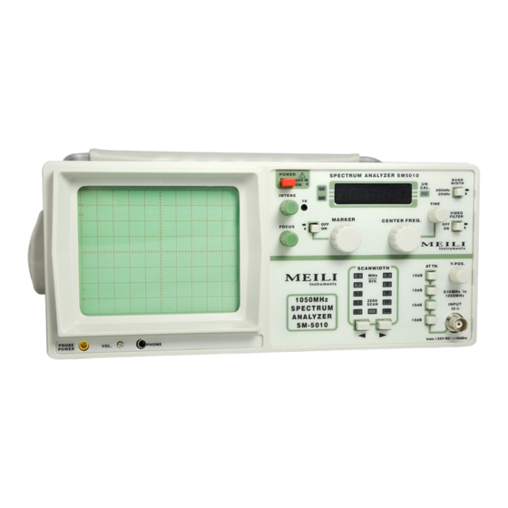
The AT5010/5011/5000 spectrum analyzers are easy
to operate.The logical arrangement of the controls
allows anyone to quickly become familiar with the
operation of the instrument, however, experienced
users are also advised to read through these
instructions so that all functions are understood.
Immediately after unpacking, the instrument should
be checked for mechanical damage and loose parts
in the interior. lf there is transport damage, the
supplier must be informed immediately. The
instrument must then not be put into operation.
Symbols
ATTENTION - refer to manual
Danger-High voltage
Protective ground (earth) terminal
Tilt handle
C
0
A
D
.
10
E
B
20
To view the screen from the best angle, there are
three different positions (C, D, E) for setting up the
instrument. If the instrument is set down on the
floor after being carried, the handle automatically
remains in the upright carrying position (A). In
order to place the instrument onto a horizontal
surface, the handle should be turned to the upper
side of the Spectrum Analyzer (C). For the D
position (10 inclination), the handle should be
turned to the opposite direction of the carrying
position until it locks in place automatically
underneath the instrument. For the E position
(20 inclination), the handle should be pulled to
release it from the D position and swing backwards
until if locks once more. The handle may also be set
to a position for horizontal carrying by turning it to
the upper side to lock in the B position. At the same
time, the instrument must be lifted, because
otherwise the handle will jump back.
Safety
This instrument has been designed and tested in
accordance with IEC Publication 1010-1, Safety
requirements for electrical equipment for
measurement, control, and laboratory use. The
CENELEC regulations EN 61010-1 correspond to
this standard. It has left the factory in a safe
condition. This instruction manual contains
important information and warnings which have to
be followed by the user to ensure safe operation and
to retain the Spectrum Analyzer in a safe condition.
The case, chassis and all measuring terminals are
connected to the protective earth contact of the
appliance inlet. The instrument operates according
to Safety Class l (three-conductor power cord with
protective earthing conductor and a plug with
earthing contact). The mains/line plug shall only be
inserted in a socket outlet provided with a protective
earth contact. The protective action must not be
negated by the use of an extension cord without a
protective conductor. The mains/line plug should be
inserted before connections are made to measuring
circuits. The grounded accessible metal parts (case,
sockets, jacks) and the mains/line supply contacts
(line/live, neutral) of the instrument have been tested
against insulation breakdown with 2200V DC.
Under certain conditions, 50Hz or 60Hz hum
voltages can occur in the measuring circuit due to
the interconnection with other mains/line powered
equipment or instruments. This can be avoided by
using an isolation transformer (Safety Class ll)
between the mains/line outlet and the power plug of
the device being investigated. Most cathode-ray
tubes develop X-rays. However, the dose equivalent
rate falls far below the maximum permissible
value of 36pA/kg (0.5mR/h).
Whenever it is likely that protection has been
impaired, the instrument shall be made inoperative
and be secured against any unintended operation.
The protection is likely to be impaired if, for
example, the instrument:
shows visible damage.
fails to perform the intended measurements.
has been subjected to prolonged storage under
unfavorable conditions (e. g. in the open or in
moist environments).
has been subject to severe transport stress (e. g.
in poor packaging).
