Comtek BST-75 Instrukcja obsługi - Strona 9
Przeglądaj online lub pobierz pdf Instrukcja obsługi dla Nadajnik Comtek BST-75. Comtek BST-75 16 stron. Synthesized base station transmitter
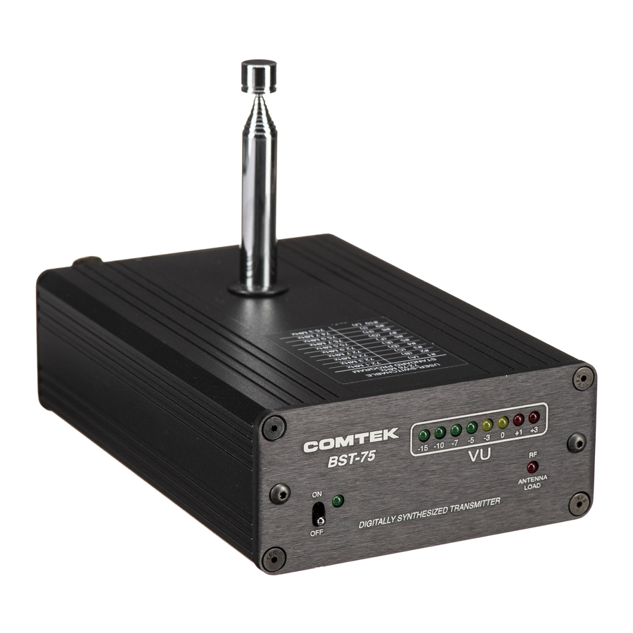
BST-75 REAR PANEL
POWER INPUT JACK: Requires 12V AC at 200 mA. Will also accept 12V
7
DC with either positive or negative center pin (for field operation only).
CHANNEL SELECTOR SWITCH: Selects the frequency on which the
8
transmitter will operate. (See Frequency Information Section.)
EXTERNAL ANTENNA JACK: BNC connector provides a standard
9
50 ohm RF output for use with an external antenna.
10
RF POWER SWITCH: Adjusts the RF power output of the transmitter
(High-120mW, Mid-40mW, Low-10mW).
AUDIO LEVEL CONTROL: This control is used to set the proper
11
modulation level when referenced with the VU meter.
12
MIC / LINE AUDIO INPUT: XLR-3 accepts balanced line level input.
1/4" phone jack accepts 2-conductor electret microphone type only.
7
8
9
10
11
12
Page 7