3onedata TNS5500D Series Skrócona instrukcja obsługi - Strona 2
Przeglądaj online lub pobierz pdf Skrócona instrukcja obsługi dla Przełącznik 3onedata TNS5500D Series. 3onedata TNS5500D Series 5 stron. 12-port series layer 2 wall mounting industrial ethernet switch
Również dla 3onedata TNS5500D Series: Instrukcja szybkiej instalacji (4 strony), Instrukcja szybkiej instalacji (4 strony), Instrukcja szybkiej instalacji (3 strony)
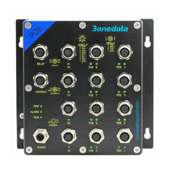
1.
Power supply indicator (P1-P2)
2.
Alarm indicator (ALM)
3.
Running indicator (RUN)
4.
Relay alarm output interface
5.
Grounding screw
6.
CONSOLE port
7.
Lugs
8.
Power input interface (P1-P2)
9.
Ethernet port indicator (E1-E8, G1-G4)
10.
Gigabit Bypass M12 interface (Two groups of
Bypass: G1-G2 and G3-G4, or G9-G10 and G11-
G12)
11.
100M PoE indicator (E1-E8)
12.
100M PoE M12 interface (E1-E8)
13.
Gigabit PoE indicator (G1-G8)
14.
Gigabit PoE M12 interface (G1-G8)
【Mounting Dimension】
Unit: mm
Notice Before Mounting:
Don't place or install the device in area near water or
moist, keep the relative humidity of the device
surrounding between 5%~95% without condensation.
Before power on, first confirm the supported power
supply specification to avoid over-voltage damaging the
device.
The device surface temperature is high after running;
please don't directly contact to avoid scalding.
【Wall-mounted Device Mounting】
On the wall of device mounting, place the device on
the wall for reference or refer to the mounting
dimension to mark two screw positions.
Hang the device on the labeled wall, align the bolt
to the labeled position, then fix them with a certain
gap.
Slide the device down to hang on the screw, then
tighten the screw, and the installation is finished.
【Wall-mounted Device Disassembling】
Power off the device.
Hold the device steadily and screw out the bolt in
the wall.
Take out the device, disassembling ends.
Notice before power on:
Power ON operation: First insert the power supply
terminal block into the device power supply interface,
then plug the power supply plug contact and power on.
Power OFF operation: First, remove the power plug, then
remove the wiring section of terminal block. Please pay
attention to the above operation sequence.
【Power Supply Connection】
Model I and Model III: 24VDC power supply
Supply supports non-polarity and redundant power
input.The power supply interface adopts M12 A-
Coded 4-Pin pin (male) connector. The pin
definitions are shown in the left figure. Power supply
input range:
Model I: 24VDC (18~36VDC).
-
Model III: 24VDC (9~36VDC).
-
model II, Model IV, Model V, Model VI: 110VDC
power supply
Supply supports non-polarity and redundant power
input. The power supply interface adopts M12 A-
Coded 4-Pin pin (male) connector. The pin
definitions are shown in the left figure. Power
supply input range: 110VDC (66~156VDC).
【Relay Connection】
This series device provides 1 M12 D-Coded 4-Pin
slot (female) that supports 1 relay alarm output. R1
and R2 are a set of normally open contacts of the
device alarm relay. They are open circuit in the state of normal
non alarm, closed when any alarm information occurs. For
example: the relay supports the output of network abnormality
alarm. It can be connected to alarm light or alarm buzzer or
other switching value collecting devices, which can timely
inform operators when the alarm occurs. The pin definitions of
relay are shown in the figure.
【Console Port Connection】
The series of device provides 1 program debugging
port based on RS232 serial port which can conduct
device
CLI
command
connecting to PC. The interface adopts M12 D-Coded 4-Pin
slot (female). The pin definitions of M12 are shown in the figure:
【Communication Interface Connection】
100M PoE M12 interface
management
after