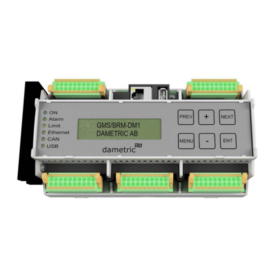
Dametric BRM-DM1 Instrukcja instalacji - Strona 4
Przeglądaj online lub pobierz pdf Instrukcja instalacji dla Jednostka sterująca Dametric BRM-DM1. Dametric BRM-DM1 6 stron. Gms basic refiner module
Również dla Dametric BRM-DM1: Podręcznik użytkownika (10 strony)

Dametric AB
5.4 Connector J2, AGS/CPM interface (option)
1,2
+24VDCin
3,4
0VDC
5,6
+24VDCout
7,8
0VDC
9,10
CAN2-H
11,12
CAN2-L
13,14
CAN2-R
15,16
CAN2-C
17,18
0VDC
19,20
0VDC
Connect K-AGP25 according to the figure. Cut away excessive
wires.
GY=grey, BU = blue, PK = pink, RD = red, SH = shield.
Connect K-AGP25 according to the figure.
(WH/BU = white / blue, BU/WH = blue /white, SH = shield
A jumper between 13 and 14 terminates the bus with 120 .
5.5 Connector J3, CMD, Digital outputs
1,2
+24VDCin
3,4
0VDC
6,8,10,12 0VDC
5
SM-WA1
7
SM-WA2
9
SM-WB1
11
SM-WB2
13
DO1
14
DO2
15
DIO3
16
DIO4
17
DIO5
18
DIO6
19
DI7
20
DI8
BRM-DM12 IM EN.docx
BRM-DM1/2
Power supply input for AGS/CPM
Power ground
Power supply output to AGS/CPM
Power ground
CAN2-interface H-signal (use twisted pair cable for
CAN2-H and CAN2-L)
CAN2-interface L-signal
CAN2-interface termination pole (jumper between 13 and 14 for 120 termination)
CAN2-interface common (for cable shielding)
Signal ground
Signal ground
The power supply input for the CMD system
The power ground
The power ground
To control motor winding
To control motor winding
To control motor winding
To control motor winding
Digital output 1
Digital output 2
Digital output 3
Digital output 4
Digital output 5
Digital output 6
Digital output 7
Digital output 8
October 14, 2019
BRM‐DM1
J2/5
J2/6
J2/7
J2/8
J2/17
BRM‐DM1
J2/9
J2/11
J2/15
J2/13
J2/14
BRM‐DM1
A+
J3/5
A‐
J3/7
B+
J3/9
B‐
J3/11
GND
J3/12
K‐CM25K
Installation manual
GY (+24V)
BU (+24V)
K‐AGP25
PK (0V)
RD (0V)
SH
WH/BU
K‐CAN1P25
BU/WH
SH
1
19
2
20
CM‐2NM...
A+
1
A‐
Step
2
B+
motor
3
B‐
4
GND
GND
Page 4 of 6
