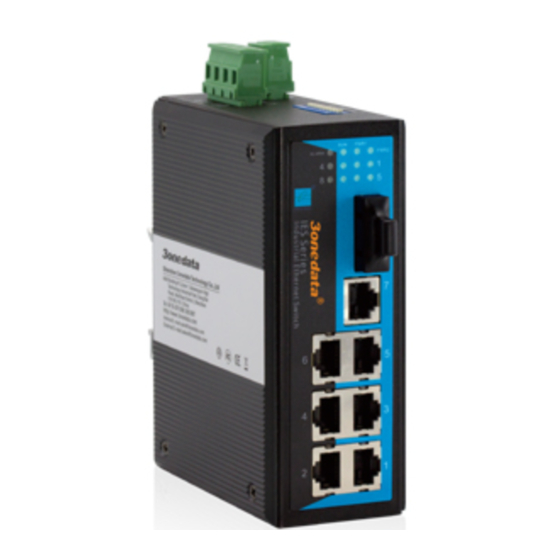
3onedata IES308-2F-P Podręcznik użytkownika - Strona 2
Przeglądaj online lub pobierz pdf Podręcznik użytkownika dla Router sieciowy 3onedata IES308-2F-P. 3onedata IES308-2F-P 4 stron. Ies308 series industrial ethernet switch

【Dimension】
The series of products are the same size, and the number of the
Ethernet interface is different. Unit (mm)
【Power supply input】
The switch have redundant power input, provides one terminal
block (4 bits) for PWR1 and PWR2 input. The redundant power
can be used single and used two self-governed power to supply to
the system, PWR1 and PWR2 input at the same time, when
neither of
these two power fails, the other power acts as a
backup, and automatically supplies power needs, ensure running
Ethernet reassuring. Voltage input range is 12~48VDC (terminal
block defined as: V1-、V1+、V2-、V2+).
【DIP Switch】
Provide 10 bits switch for function setting. 1~8 alarm enable
switch setting, ON show enable. 9 show PWR2 alarm setting, 10
show PWR 1 alarm setting, ON show alarm state.
【Relay connection】
The relay consists of the two middle contacts of the terminal
block on the switch's top panel. The two terminal block connector
are used to detect both power faults and port faults. The two wires
attached to the Fault contacts form an open circuit when:
(1) The switch have lost power from one of the DC power inputs.
(2) One of the ports for which the corresponding Port alarm DIP
Switch is set to ON is not properly connected.
If neither of these two conditions occurs, the alarm circuit will be
closed.
【Communication connector】
10/100BaseT(X) Ethernet port
The pinout define of RJ45 port display as below, connect by UTP
or STP. The connect distance is no more than 100m. 100Mbps is
used 120Ωof UTP 5, 10Mbps is used 120Ωof UTP 3 ,4, 5.
RJ 45 port support automatic MDI/MDI-X operation. can
connect the PC, Server, Converter and HUB .Pin 1,2,3,6
Corresponding connection in MDI. 1→3, 2→6, 3→1, 6→2 are
used as cross wiring in the MDI-X port of Converter and HUB.
10Base-T/100Base-TX are used in MDI/MDI-X, the define of Pin
in the table as below.
NO.
MDI signal
1
TX+
2
TX-
1
8
3
RX+
6
RX-
—
4, 5, 7, 8
Note: "TX±" Transmit Data±, "RX±" Receive Data±, "—" Not use.
- 2 -
10/100Base-T(X) MDI (straight-through cable)
10/100Base-T(X) MDI-X (Cross over cable)
MDI/MDI-X auto connection makes switch easy to use for
customers without considering the type of network cable.
100Base-FX Fiber port
100Base-FX full-duplex SM or MM port, SC/ST/FC type .The
fiber port must be used in pair, TX (transmit) port connect remote
switch's RX(receive) port; RX(receive) port connect remote
switch's TX(transmit) port.
The optical fiber connection supports the line to instruct
enhance the reliability of network effectively.
Suppose: If you make your own cable, we suggest labeling
the two sides of the same line with the same letter (A-to-A and
B-to-B, shown as below, or A1-to-A2 and B1-to-B2).
MDI-X signal
RX+
RX-
TX+
TX-
—
