3onedata IES618-4F-P Podręcznik użytkownika - Strona 2
Przeglądaj online lub pobierz pdf Podręcznik użytkownika dla Router sieciowy 3onedata IES618-4F-P. 3onedata IES618-4F-P 5 stron. Ies618 series industrial ethernet switch
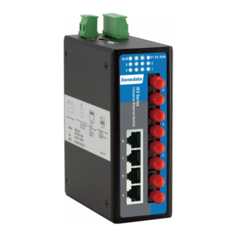
Front panel view
IES618
IES618-3F
1. DIP switches for default factory
2. Console port
3. 2-pin terminal block for relay output
4. Ground screw
5. Power input terminal block
6. Screw holes for Wall Mounting Kit
7. DIN-Rail mounting kit
8. Relay alarm LED
9. Power indicator (PWR1, PWE2)
10. System running LED
11. Link/ACT LEDs
12. 10Base-T /100Base-TX Ethernet port
13. 100Base-FX fiber port
【Power supply input】
DC Series Switch:
The switch have redundant power input, provides one terminal
block (4 bits) for PWR1 and PWR2 input. The redundant power
IES618-2F
can be used single and used two self-governed power to supply to
the system, PWR1 and PWR2 input at the same time, when
neither of these two power fails, the other power acts as a backup,
and automatically supplies power needs, ensure running
Ethernet reassuring. Voltage input range is 12~48VDC (terminal
block defined as: V1-、V1+、V2-、V2+).
AC Series Switch:
IES618-4F
The Industrial Ethernet switches have singe power and
redundancy power two kinds of power input. The singe power AC
series
top
100~240VAC/DC power entered (L/+, FG, N/-)
Important notice:
1. Power ON operation: first of all, insert power cable's terminal
block into device's power port, then insert power supply plug into
power source
2. Power OFF operation: First off all, unpin power plug, then
strike the terminal block, please take care of operation sequence.
【Dimension】
panel
provides
3
bit
terminal
block
- 2 -
The series of products size is the same, and the type of the
Ethernet interface is different. Unit (mm)
【DIP Switch】
Top panel provided 4 bits DIP switch to do function configure
(ON to enable effective),1 and 4 keep for future function. 2 is
for upgrade. 3 is recovery default factory. Please power off and
power on when you change the status of DIP switch.
【Relay connection】
for
Relay access terminals in the top panel of the device. Between the
two terminal relay, as an open circuit state in normal non alarm
state, when there is any alarm information to the closed state. The
two terminal block connector are used to detect both power failure
and port failure. The two wires attached to the Fault contacts form
an open circuit when the device has lost power supply from one of
the DC power inputs or one of the ports is failure. (Note: The AC
power switch does not support power alarm.)