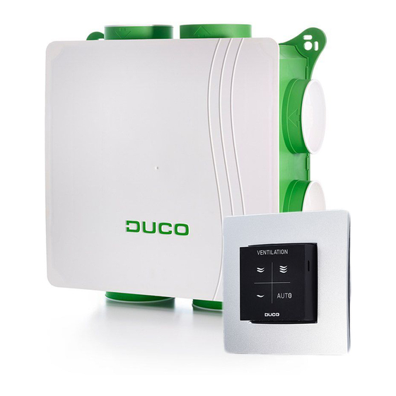
Duco DucoBox Focus Instrukcja instalacji - Strona 6
Przeglądaj online lub pobierz pdf Instrukcja instalacji dla Jednostka sterująca Duco DucoBox Focus. Duco DucoBox Focus 16 stron.
Również dla Duco DucoBox Focus: Podręcznik użytkownika (2 strony), Instrukcja instalacji (20 strony), Szybki start (4 strony)

ENGLISH
RF (wireless communication)
RF components have a maximum free-field range of 350 metres� This dis-
tance will be much less in a building because of obstacles� Therefore, you will
need to take objects such as walls, concrete and metal into account� All slave
components (except those which are battery powered) also act as repeaters�
Signals from components that are unable to make a (strong) connection with
the master component are forwarded automatically via no more than one other
non-battery-powered component (= hop)� Please refer to information sheet
RF communication (L8000018) at www�duco�eu for further information�
Wired (cabled communication)
Wired components can be daisy-chained (= recommended)� This means that a
separate cable will not be required for each component� A single central power
supply can be used�
The cable required is a 5 x 0�75 mm² data cable� We strongly advise using a
shielded cable� This is to prevent any interference that may affect the data com-
munication� Any Tronic window ventilators will be supplied with a 5 x 0�25 mm²
cable which can be connected via a splicing terminal block�
04 Control valves
The control valves, whether or not they are fitted with a sensor for measuring CO or humidity, can be built into the DucoBox Focus�
Together with the fan, they ensure the correct exhaust air flow rate in the right room�
A control valve with combined CO
version of 11.2 or higher.
A DucoBox Focus can contain up to a maximum of 7 control valves (= one per intake duct)� This can be expanded to a maximum of
11 control valves by using the 'Control Valve Manifold' (item 0000-4454)�
A control valve must always be provided for each ventilation duct connected!
04.A Mounting the control valves
Slide the control valve into the locations
provided in the DucoBox Focus� Connect
the 'VALVE' connector on the DucoBox
to IN on the control valve� If applicable,
connect OUT on the valve to IN on another
control valve to be added� At least one
valve must be connected to the DucoBox at
any time�
TIP: Use the letter labels on the DucoBox
and the valves (A/B/C/D/E/F/G) to give
these the same letter, so that the valves
always remain in the same position�
6
L2000631 Installation guide for DucoBox Focus (Revision L | 06.09.2022)
and RH measurement can only be used with a DucoBox Focus with a software
2
DucoBox
IN
OUT
VALVE1
IN
OUT
IN
OUT
Power supply
Wiring
Frequency
Maximum distance
Maximum number
of components
Power supply
Wiring
Maximum distance
Maximum number
of components
IN
OUT
VALVE2
IN
OUT
OUT
G G
F F
A A
E E
B B
D D
C C
DUCO RF
230 VAC
1,5 mm²
868 Mhz
350 m, free field (less
through obstacles)
Up to 25 wireless
components in a
single system
DUCO WIRED
24 VDC
5 x 0,75 mm²
(5 x 0�25 mm² from Tronic
window ventilators)
up to 300 m
Up to 99 wired
components in a
single system
IN
IN
IN
IN
OUT
OUT
OUT
OUT
