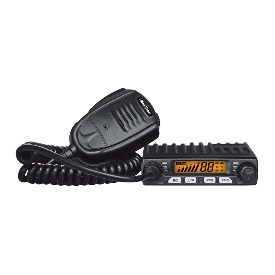
AnyTone SMART Instrukcja obsługi - Strona 2
Przeglądaj online lub pobierz pdf Instrukcja obsługi dla Radio AnyTone SMART. AnyTone SMART 3 stron. 10 meter amateur mobile radio
Również dla AnyTone SMART: Podręcznik użytkownika (9 strony)

2.HOW TO USE THIS RADIO
2.6 Mode control
.......................................................................................
1. Short press
key to switch between AM /FM mode.
2. The LCD displays the selected mode.
2.7 RF Gain contro
....................................................................................
1. Short press
key, LCD displays RFG and the present RF gain level
flashes.
2. Short press microphone [ UP ] or [ DN ] to change level.
3. Short press [PTT] switch to exit RF gain level control.
» » Note:When»RFG»function»is»on»the»LCD»displays»RFG,»if»RFG»level»is»6»
means»the»attenuation»»is»6dBm.
2.8 Emergency Channel
..........................................................................
1. Short press
key to choose CH9, the channel number flashes.
2. Short press
key again to choose CH19, the channel number
flashes.
3. Short press
key third time to return to last normal channel.
2.9 Keypad Lock
........................................................................................
1. Hold
key for over 3 seconds to lock the keys, LCD displays "
2. Hold
key for over 3 seconds again to unlock the keys, "
disappears form LCD.
» » Note:In»lock»Mode»all»keys»except»PTT»is»valid.
2.10 VOX control
........................................................................................
1. Press and hold [PTT] switch;
2. Short press
key to activate or deactivate the VOX function. " " is
displayed when the function is active.
» » Note:The» VOX» function» allows» transmitting» by» speaking» into» the»
original»microphone»without»pressing»the»PTT»switch.
» » In»order»to»prevent»the»VOX»function»from»being»triggered»by»mistake,»
the»radio»will»automatically»turn»off»the»VOX»function»after»it»is»powered»
off.
2.HOW TO USE THIS RADIO
2.11 VOX Setting
........................................................................................
1. Turn on the power while pressing
setting. " " flashes in the LCD.
2. Short press
key to choose wanted setting.
LX: stands for sensitivity level. allows the adjustment of the microphone for
an optimum transmission quality. Adjustable level form 1 (high sensibility)
to 9 (low sensibility)
tX: stands for delay time. allows avoiding the sudden cut of the transmission
by adding a delay at the end of speaking. The level is adjustable form 1
(short time delay) to 9 (long time delay)
3. Short press microphone [ UP ] or [ DN ] to set desired level.
4. Hold
key to store and exit setting.
2.12 Scan function
.....................................................................................
1. Hold
to start scan function, "SC" falshes in the LCD;
2. Press microphone [ UP ] or [ DN ] to change scan direction during scan;
3. Hold
or short press [PTT] switch to exit scan function.
2.13 Norms control
....................................................................................
1. Hold
to power on radio, until LCD displays the norms;
".
2. Press microphone [ UP ] or [ DN ] to choose wanted norms;
"
3. Power off and power on again.
2.14 Install external speaker
...................................................................
Choose a 16Ω external speaker with 3.5mm mono connector.
» » WARNING:The»sound»output»mode»of»the»machine»is»BTL»output,»and»
the»two»pins»of»the»speaker»cannot» be»connected» to»the»ground»net» or»
the»machine»shell!»Otherwise,»there»will»be»a»large»DC»current»fl»owing»
through»the»speaker,»which»will»burn»the»speaker»and»components.
2.15 Resume factory default
....................................................................
1. Hold
key to power on radio, until the LCD displays "rt", the resume
work finish.
2. All channel and function setting will resume factory default after above
operation.
3
3 . SPECIFICATION
key enter the VOX function
Modulation Mode
Frequency Range
Frequency Tolerance
Input Voltage
Dimensions
Weight
Operating Temperature Range
Current Drain
Antenna Connector
Power Output
Transmission interference
Frequency Response
Modulated signal distortion
Output Impedance
Sensitivity
Image Rejection
Adjacent Channel Rejection
IF Frequencies
Automatic Gain Control(AGC)
Squelch
Audio Output Power
Frequency Response
4
GENERAL
AM
26.965-27.405MHz
±5.0ppm
12V
140x161.5x41mm
608g
-20℃ to +50℃
Transmit
3A MAX
Receive
Squelched 0.3A
VOL Max
0.7A
UHF, SO-239
TRANSMITTER
4 Watts AM
inferior to 4nW
300-3000Hz
inferior to 5%
50 ohms
RECEIVER
Less than 1uV for 10dB(S+N)/N
70dB
60dB
1st 10.695MHz
2nd 455KHz
Less than 10dB change in audio
Output for inputs from 10 to 50000uV
less than 1uV
1Watts at 8Ω less than 10% distortion
300-3000Hz
A1.210308
5
