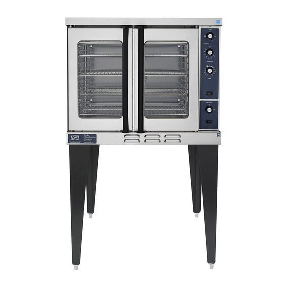
Duke E SERIES Instrukcja instalacji, obsługi, części i konserwacji - Strona 5
Przeglądaj online lub pobierz pdf Instrukcja instalacji, obsługi, części i konserwacji dla Piekarnik Duke E SERIES. Duke E SERIES 15 stron. Electric convection oven e - series

D.
Electrical Connections
Your oven is supplied for connection to a 208, 240 or
480 volt grounded circuit. The electric motor, oven
lights, indicator lights and control circuits are connected
internally and require no seconday power supply
Before making any connections to these units, check
the rating plate to assure that the voltage and phase of
the oven is compatible with the electrical supply. When
installing, all ovens must be electrically grounded in
accordance with local codes, or in the absence of local
codes, with the National Electrical Code,
70-1990 (in Canada -
diagrams are located in the control compartment area of
the oven and at the back of the oven. Standard wiring
schematics are also provided with this manual.
NOTE TO ELECTRICAL INSPECTOR:
Inspection of electrical connection should be
accomplished by the removal of the lower finishing
piece.
This is done by loosing the four screws
located in the door opening under the doors.
E.
Ventilation
Proper ventilation is very important for the proper
function of your oven. A good ventilation system will
allow the oven to function properly as well as remove
unwanted vapors. Not venting the ovens properly can
result in unsatisfactory baking results as well as the
possibility of damaging your oven. To keep your
warranty in force, a proper ventilation system must be
employed.
Venting to a Canopy Exhaust Hood
The best way to vent your oven is by placing it under a
properly designed mechanically driven exhaust hood.
The hood should be sized so the equipment which it is
designed to ventilate fits underneath with a minimum
six (6) inch (152 mm) overhang on all sides not
adjacent to a wall. The distance from the floor to the
lower edge of the canopy should not exceed seven (7)
feet (2.2
m).
The hood should have adequate capacity and provide a
sufficient supply of make up air. Ventilation hoods
come in many sizes and capacities. Hood capacity is
expressed in cubic feet per minute
make-up and exhaust air required for the canopy hood
should be about 22 CFM per oven section. Information
for the proper construction and installation of
ventilating hoods may be obtained from the "Standard
for the Installation of Equipment for the Removal of
Smoke and Grease-Laden Vapors from Commercial
ANSI/NSPA
CSA Std. C-22.1).
Wiring
(CFM).
The total
Cooking Equipment,
NFPA-96-1980".
F. Oven Assembly
Before assembling and installing the oven, please check
to make sure that all necessary parts are present. In
addition to the oven itself, there will also be legs, feet or
casters, the vent guard, (for double sectons, retaining
clips vent riser) and miscellaneous hadware.
check the interior of all oven sections for the parts
needed to assemble and install your
Leg Attachment
• Once the oven has been removed from the
carton, lay it on its left side (the side without the
controls), hold the leg and align with the
threaded holes in the front comer of the bottom
of the oven. Carefully start the threads of the
comer leg bolt (5/16"-18
threading.
• Align the leg plate holes in each leg with those
in the comers of the oven bottom and secure
using two
5/
bolts firmly. Repeat this procedure for all legs.
•
Raise the oven up on its legs.
Level the oven by turning the adjustable feet in or out as
needed.
Caster Installation
• Casters are available as an option for both the
single and double oven sections.
• The installation of casters requires the removal
of the adjustable feet from the legs. This is done
by placing the bit of a large screwdriver against
the lip of the foot and rapping the screwdriver to
drive the foot out of the leg. The caster is then
inserted fully into the opening where the foot
came out and the locking nut tightened to expand
the compression sleeve of the caster.
NOTE: The casters with locking brakes are best
mounted on the front side of the oven for easier
access.
If you plan to use casters, a fixed reatrant of the
proper length is recommended to eliminate strain on
the connecting wire. If the oven is revoed from its
normal position, the restraint must then be
reattached when returned.
5
oven(s).
X 1/2"),
avoid cross
16"-18
x
1/2" bolts. Tighten all
Please
