cashco DA2 Instrukcja instalacji, obsługi i konserwacji - Strona 7
Przeglądaj online lub pobierz pdf Instrukcja instalacji, obsługi i konserwacji dla Kontroler cashco DA2. cashco DA2 16 stron. Direct-acting, positive bias differential pressure reducing regulator
valve plug (20) in a bench vise, grasping
the milled flats directly under the seat disc
section of the plug (20). DO NOT clamp
the machined lower spindle area of the
plug (20) in the vise. The lower spindle
area must slide smoothly in the lower
guide bushing (24), therefore it cannot be
marred. Loosen the piston-guide bearing
(13) by turning CCW. A double-posted
spanner wrench should be used to allow
for easy loosening and correct reassembly
(see Double-Posted Spanner Wrench in
Section IX). Remove the valve plug from
the vise and complete the unthreading
of the valve plug from the piston-guide
bearing. Remove the valve plug from the
lower end of the cage (19) and remove
the piston-guide bearing from the upper
end of the cage.
2. Examine the com po nents (27.1, 27.2, 27.3,
27.4, 27.5) of the dy nam ic side seal (27)
mechanism to de ter mine if significant leakage
was oc cur ring. If the dy nam ic side seal (27)
shows signs of sig nif i cant leakage, de ter mine
if op er at ing con di tions are ex ceed ing pres sure,
pressure drop, or tem per a ture limits.
Remove dynamic side seal (27) components.
Special care should be tak en when using
"tools" to remove the components to ensure
that no scratches are imparted to any portion
of the piston-guide bearing (13) groove.
3. Remove wiper seal (16), if supplied, from
within cage (19).
4. Remove wiper washer (17.1), camber adjust-
ing washer (17.2), or seal retainer (17.3), if
sup plied, from within cage (19).
5. Remove o-ring lower stem seal (14.3) from
plug (20).
6. Remove seat ring (21); examine for signs
of leakage. If seat ring (21) shows signs of
significant leakage, determine if op er at ing
con di tions of pressure, pres sure drop, or
temperature are ex ceed ing lim its.
7. Clean all reusable metal parts according to
owner's pro ce dures. NOTE: On regulators
originally supplied as Special Cleaning Op-
tion-55, -56, or -57, maintenance must include
a level of clean li ness equal to Cashco clean-
ing standards of #S-1134, #S-1542, #S-1589
re spec tive ly. Con tact factory for de tails.
IOM-DA2
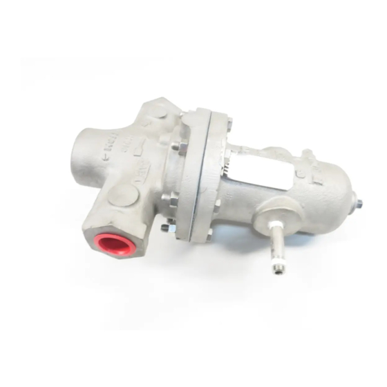
"Flats"
Figure 3: Assembled ITA,
Metal Diaphragm Construction
D. Inspection of Parts:
1. After inspection remove from the work area
and dis card the old "soft goods" parts (i.e.
o-rings, di a phragms, seals, gaskets, etc.).
These parts MUST be re placed with fac to ry
supplied new parts.
2. Inspect the metal parts that will be reused. The
parts should be free of surface contaminants,
burrs, oxides, and scale. Rework and clean the
parts as necessary. Sur face con di tions that
affect the regulator per for mance are stated
below; replace parts that can not be re worked
or cleaned.
3. QC Requirements:
a. Valve plug (20);
1. 16 rms finish on its seating surface
for tight shutoff.
2. No major defects on bottom guide
spin dle.
b. Cage (19);
1. 16 rms finish on cylinder bore. No
"ledges" formed due to wear from
moving dynamic side seal (27) or
wiper seal (16).
c. Lower guide bushing (24) (non-
replaceable on 1/2" - 2" sizes):
1. 16 rms finish on bore.
2. Max 0.015 inch (0.38 mm) clearance
be tween valve plug (20) spindle and
lower guide bushing (24).
d. Internal sensing drilled plug (32);
1. Ensure that bore is minimum 0.125
inch (3.20 mm). Clean or drill out as
required.
4. Staging Material for Reassembly.
a. Inspect and clean parts, as necessary,
from the spare parts kit. (See Article
VII.A.4. comments concerning cleaning
for ox y gen service.)
b. Lay out all the regulator parts and check
against the bill of material.
13
27
15
17
19
21
20
7