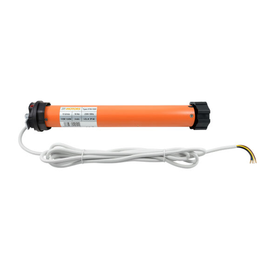
3T-Components 3T-MOTORS 3T35-SD Instrukcja instalacji i obsługi - Strona 11
Przeglądaj online lub pobierz pdf Instrukcja instalacji i obsługi dla Silnik 3T-Components 3T-MOTORS 3T35-SD. 3T-Components 3T-MOTORS 3T35-SD 16 stron. Shutter motors with mechanical limit switches, for shafts from 60/40 mm

INSTALLATION INSTRUCTIONS
Setting the end positions:
8
Explanation of the limit switch screws
There are 2 limit switch screws on the motor head. One limit switch screw is responsible for the upper end position, the other for the lower end position.
The end positions can be adjusted by turning the limit switch screws with the adjustment pin.
Motor type 3T45-SD
The arrows with PLUS and MINUS apply to both limit switch screws and show you in which direction you must turn the adjusting pin to switch
off the motor sooner or later. Turning the limit switch screw in the PLUS direction after switching off allows the motor to continue moving step
by step in the corresponding direction. Turning the limit switch screw in the MINUS direction during travel causes the motor to switch off earlier.
Motor type 3T35-SD
Left installation
Motor type 3T45-SD
Limit switch screw white:
Lower end position
Limit switch screw red:
Upper end position
Left installation
Motor type 3T35-SD
Limit switch screw white:
Lower end position
Limit switch screw red:
Upper end position
The straight up and down arrows (only motor type 3T35-SD)
indicate the direction of rotation of the motor and shaft and thus
show you for which end position the limit switch screw next to it is
responsible. Depending on whether the direction of rotation leads
to unrolling or rolling up of the roller shutter, the limit switch screw
is responsible for the lower or upper end position (unrolling >
lower end position, rolling up > upper end position).
Right installation
Limit switch screw red:
Lower end position
Limit switch screw white:
Direction of rotation
Limit switch screw
Upper end position
Right installation
Limit switch screw red:
Lower end position
Direction of rotation
Limit switch screw white:
Limit switch screw
Upper end position
Adjustment pin
3T-MOTORS Tubular motors | Installation instructions
11
