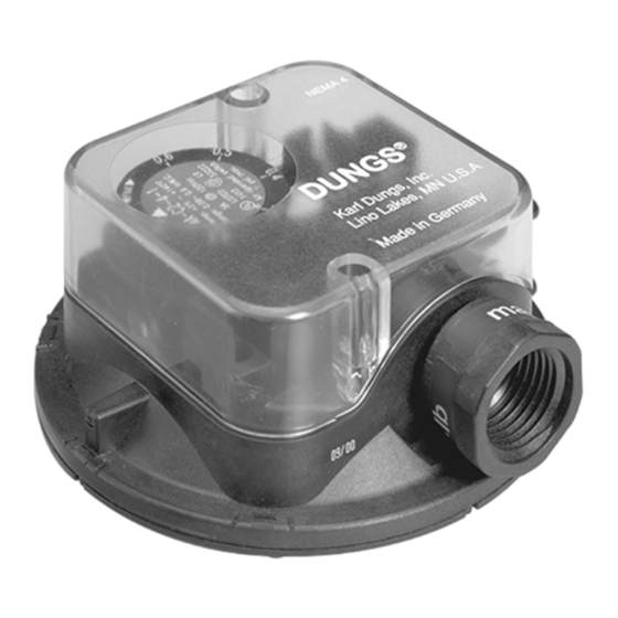
Dungs AA C2 Series Instrukcje instalacji - Strona 3
Przeglądaj online lub pobierz pdf Instrukcje instalacji dla Przełącznik Dungs AA C2 Series. Dungs AA C2 Series 4 stron. Differential air pressure switch

• Remove the clear cover from the switch.
• Use 14 or 16 AWG wire rated for at least 75°C.
• Route the wires through the conduit connector.
• Connect the wiring to the appropriate screw terminals.
• Replace the clear cover.
CAUTION: All wiring must comply with local electri-
cal codes, ordinances and regulations.
CAUTION: Do not exceed the switch ratings given in
the specifications and on the switch.
Adjusting the Set Point
• Mount switch in the intended operation position.
• Remove the clear cover from the switch.
• Adjust the set point to the desired set point pressure by
turning the dial until the desired pressure is opposite the
white arrow on the blue dial face.
• After adjusting the set point for normal operation check to
see that the pressure switch operates as intended.
Annually check the switch for proper operation
Set Point Calibration
•
Connect a meter capable or reading +/- 0 ohms to the
NC and COM contacts.
•
Measure the resistance across the NC and COM con-
tacts. If the resistance is more than 1 ohm, the switch
switch should be replaced, since this indicates that the
switch contacts are starting to either corrode or carbon-
izing.
3 ... 4
WIRING
AA...C2 switching function
As pressure rises:
1 NC opens, 2 NO closes
As pressure falls:
1 NC closes, 2 NO opens
OPERATION
• Use an accurate pressure gauge connected upstream from
the switch to measure the actual pressure.
• Replace the clear cover.
Automatic Reset
The NC contact of the AA...C2 breaks when pressure rises
above the set point. It makes automatically when pressure
falls below set point.
MAINTENANCE
•
Apply appressure to the + air pressure connection, and
confirm that the NC contact breaks when pressure rises
above the set point and that the NO contact makes. the
NC contact will make automatically when pressure falls
below the set point pressure.
•
Connect a meter capable or reading +/- 0 ohms to the
NO and COM contacts.
•
Measure the resistance across the NO and COM con-
tacts. If the resistance is more than 1 ohm, the switch
switch should be replaced, since this indicates that the
switch contacts are starting to either corrode or carbon-
izing.
