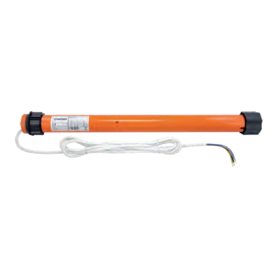
3T-Components 3T-MOTORS 3T45-30E Instrukcja instalacji i obsługi - Strona 6
Przeglądaj online lub pobierz pdf Instrukcja instalacji i obsługi dla Silnik 3T-Components 3T-MOTORS 3T45-30E. 3T-Components 3T-MOTORS 3T45-30E 12 stron. Shutter motors with obstacle detection and electronic limit switches

INSTALLATION INSTRUCTIONS
Please note:
The motor can be installed on the right-hand side as well as on the left-hand side.
•
If the direction of rotation is reversed, please exchange the wires for the up and down direction.
The setting of the end positions is only possible in the installed state (motor in shutter shaft).
•
Never place screws in the area of the tube motor, as they will damage the motor.
•
Engine damage caused by improper use or unprofessional installation,
•
lead directly to loss of warranty.
INSTALLATION SHUTTER MOTOR
Installation situation
1
Counter
bearing*
2
Ball
bearing*
3
Roller
capsule*
4
Shutter
shaft*
5
Suspension
spring*
6
Shaft adapter
7
Tubular motor
8
Limit switch adapter
9
Engine mount
10
Shutter
curtain*
*
Accessories; not included
Prepare power connection:
1
The mains connection cable of the drive must be laid internally in the empty conduit up to the junction box.
•
The local electrical regulations must be observed.
Remove shutter shaft:
2
Lower the roller shutter.
•
Open the cover of the roller shutter box and release the suspension springs from the roller shutter shaft.
•
Lift roller shutter shaft incl. ball bearing out of the holder.
•
1
2
3
4
5 6
7
8
3T-MOTORS Tubular motors | Installation instructions
9
10
6
