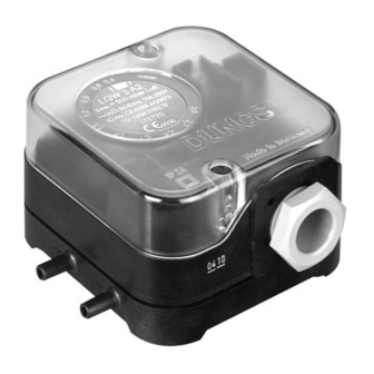
Dungs LGW A2 Series Instrukcja obsługi i montażu - Strona 4
Przeglądaj online lub pobierz pdf Instrukcja obsługi i montażu dla Przełącznik Dungs LGW A2 Series. Dungs LGW A2 Series 6 stron. Air pressure switch, air pressure switch with test button
Również dla Dungs LGW A2 Series: Instrukcja obsługi i montażu (8 strony), Instrukcja obsługi i montażu (8 strony), Instrukcja obsługi (12 strony)

Schaltfunktion
Bei steigendem Druck
1 NC öffnet
2 NO schließt
Bei fallendem Druck
1 NC schließt
2 NO öffnet
Elektrischer Anschluß
IEC 730-1 (DIN EN 60 730 T1)
Über Kabeleinführung PG 11, mit
zugentlasung, an Schrauben-
klemmen für Kabel Ø7 bis
Ø12,5mm.
Berührschutz ist
nicht grundsätz-
lich gewährlei-
stet, Kontakt mit
spannungsfüh-
renden
Teilen
möglich!
Zur Erhöhung der Schaltleistung
wird bei DC-Anwendungen
< 20 mA und DC 24 V der Einsatz
eines RC-Gliedes empfohlen.
Raccordement électrique
IEC 730-1 (DIN EN 60 730 T1)
Raccordement sur bornier à vis par
PG 11 pour câble de Ø 7 à 12,5 mm.
La
protection
n'est pas garan-
tie, contact avec
des pièces sous
tension possible!
Pour augmenter la puissance de
rupture, l'utilisation d'un circuit
RC est préconisée pour les appli-
cations à courant continu< 20
mA et =(DC) 24 V.
Prüftaste
nur LGW...A2P
Bei anstehendem Druck wech-
selt der Schalter durch Drücken
(Entlüften der unteren Kammer)
der Prüftaste p+ von NO nach
NC. Prüftaste ca. 5 s gedrückt
halten. Wird die Prüftaste freige-
geben wechselt der Schalter von
NC nach NO.
Prüf-
taste
p+
Prüftaste
Test button
Touche de contrôle
Tasto di prova
Switching function
While pressure is increasing
1 NC opens
2 NO closes
While pressure is decreasing
1 NC closes
2 NO opens
Electrical connection
IEC 730-1 (DIN EN 60 730 T1)
Via cable input PG 11, with rubber
grommet suitable for cables be-
tween 7 and 12.5 mm diameter.
There is no protec-
tion against acci-
dental
contact.
Contact with live
parts is possible!
To increase the switching capacity,
we recommend that you use a RC
device for current values
< 20 mA and 24 V d.c. applications.
Allacciamento elettrico
IEC 730-1 (DIN EN 60 730 T1)
Con passacavo PG 11, con scari-
co della trazione, collegato a mor-
setti a vite per cavi Ø 7 fino
Ø12,5 mm.
Non é sostanzial-
mente garantita la
protezione da sca-
riche, é possibile il
contatto con con-
duttori di tensione.
Per aumentare la potenza d'inseri-
mento con applicazioni DC < 20
mA e 24 V, consigliamo l'impiego
di un elemento RC.
Test button
only LGW...A2P
When pressure is present, the
switch changes from NO to NC
when test button p+ is pressed
(vents lower chamber). Press test
button for about 5 s. When the test
button is released, the switch
changes from NC to NO.
Schéma de fonctionnement
Pression montante
1 NC ouvre
2 NO ferme
Pression decendante
1 NC ferme
2 NO ouvre
2
NO
COM
3
1
NC
p
N
optional
für optische Schaltanzeige (LED,
Glimmlampe)
Optional
for visual display (LED, filament
lamp)
en option
Contrôle de position (par LED
lampe fluorescente)
opzione
per visualizzazione di comando
ottica (LED, lampadina a baglio-
re)
optional
optional
en option
opzione
DIN 43 650 A
2
1
NC
NO
3
COM
Touche de contrôle
uniquement LGW...A2P
Sous pression le switch commute
de NO vers NC lorsque l'on appuie
sur la touche de contrôle p+ (dé-
compression de la chambre infé-
rieure). Maintenir appuyée la tou-
che de contrôle pendant 5 s envi-
ron. Si l'on relâche la touche de
contrôle, le commutateur passe de
NC à NO.
Prüf-
taste
Prüf-
taste
5 s
2
NO
2
NO
COM
COM
3
3
1
NC
1
NC
p
p
Funzione di commutazione
Con pressione in salita
1 NC apre
2 NO chiude
Con pressione in discesa
1 NC chiude
2 NO apre
2 NO
1 NC
N
3 COM
PG 11
Tasto di prova
solo LGW...A2P
Premendo il tasto di prova p+
(deaerazione della camera infe-
riore), con presenza di pressio-
ne, l'interruttore commuta da NO
a NC.Tenere premuto il tasto per
ca. 5 s. Lasciando libero il tasto
l'interruttore commuta da NC a
NO.
Prüf-
taste
2
NO
COM
3
1
NC
p
4 ... 6
