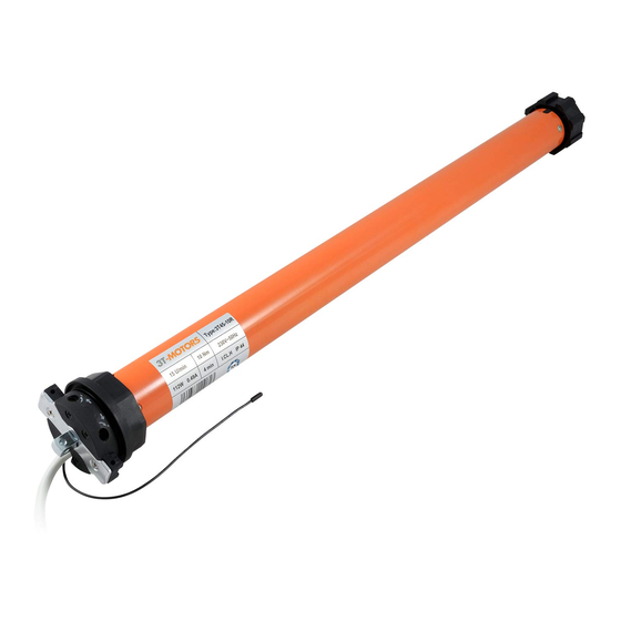
3T-Components 3T-MOTORS 3T45-50R Instrukcja instalacji i obsługi - Strona 14
Przeglądaj online lub pobierz pdf Instrukcja instalacji i obsługi dla Silnik 3T-Components 3T-MOTORS 3T45-50R. 3T-Components 3T-MOTORS 3T45-50R 20 stron. Radio shutter / awning motors with mechanical limit switches
Również dla 3T-Components 3T-MOTORS 3T45-50R: Instrukcja instalacji i obsługi (20 strony)

INSTALLATION INSTRUCTIONS
Slide the side bearing with universal bearing onto the support tube & fasten.
•
Ensure that the motor square spigot is properly engaged in the universal bearing.
•
Secure the motor square spigot with the supplied cotter pin.
•
Attach the cover to the side bearing.
•
Install awning & release fuses.
•
3.9
Support tube
Side bearing &
Universal bearing
Awning motor wiring:
4
Connect the radio awning motor to the mains.
•
The electrical connection of the awning motor and control may only be carried out by qualified personnel.
•
If the motor runs in the opposite direction after installation, the direction of rotation of the radio motor must be changed
•
via the radio transmitter (p. 16).
Power grid
230 V / 50 Hz
1) brown / black = L1 / Phase
2) blue = N Neutral conductor
3) green/yellow = PE Protective conductor
Programming radio transmitter
5
Teach radio transmitter to shutter motor. See Programming radio transmitter > Teaching hand-held transmitter to 3T radio motor type R (page 16).
•
If the direction of rotation is reversed, please change it with the taught-in radio handheld transmitter > Change direction of rotation of radio motor (page 16).
•
>
fig. 3.11
>
fig. 3.12
3.10
1 (L1)
2 (N)
3 (PE)
>
fig. 3.9
>
fig. 3.10
3.11
Cotter pin
3.12
Cover
Radio awning motor
230 V / 50 Hz
1 (L1)
2 (N)
3 (PE)
1) brown / black = L1 / Phase
2) blue = N Neutral conductor
3) green/yellow = PE Protective conductor
3T-MOTORS Radio tubular motors | Installation instructions
Side bearing
14
