Dungs DMA Instrukcje instalacji - Strona 2
Przeglądaj online lub pobierz pdf Instrukcje instalacji dla Kontroler Dungs DMA. Dungs DMA 3 stron. Motor actuator, butterfly control valve

Wiring the DMA
1. Remove all power supplies.
2. Use minimum AWG #16 class 1 wiring for all terminals.
3. Remove cover to access the terminal block.
4. Only use the specified terminals. Terminal 8 must
be the + input and terminal 10 must be the - input.
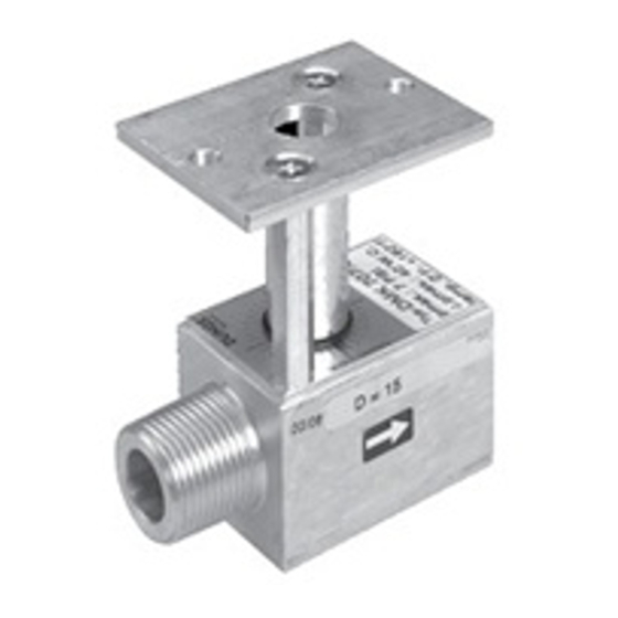
Mounting DMA to a DMK/6 butterfly valve
1. Remove the clear cover from the DMA
2. Insert the shaft from the DMA into the linkage
of the DMK/6 until the motor is flush on the DMK/6
mounting plate. snug the set screw with a 2.5 mm
allen wrench. Torque to 15 lb-in.
3. Insert the M5 X 55 mounting bolts (supplied)
through the DMA motor mounting holes. Take care
not to break the plastic covers off of the bolt holes.
Hand tighten the 8mm hex nuts that are supplied.
Torque the bolts to 45 lb-in.
Mounting the DMK/6 to a shutoff valve
1. Turn off the gas supply.
2. Refer to the flow direction on the valve housing.
3. Note: Aluminum to Aluminum connection:
Coat inner and outer threads with a suitable
lubrcant before sealing the inner and outer threads.
4. DO NOT use any part of the DMA or the mounting
bracket of the DMK/6 assembly as a lever to
tighten! Use appropriate sized wrench.
5. Tighten connections. Use the chart below for
torque specifications.
6. Perform a complete leak test after installation.
WIRING
5. The cover has an intergrated protective barrier that
6. For terminals 8 and 10, use properly sheilded wires, that
Terminal Block for DMA
MOUNTING
DMK
707
710
Max. lb-in 560
750
physically separates the wiring from the moving
adjustment switches and cams. Wiring must be
properly routed so that the cover can be installed.
are grounded on both sides, and run through conduit
containing only low voltage (24V) wiring.
712
715
720
875
940
1190
2 ... 3
