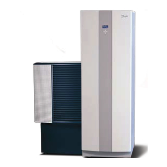
Danfoss DHP-A Instrukcja instalacji - Strona 12
Przeglądaj online lub pobierz pdf Instrukcja instalacji dla Jednostka sterująca Danfoss DHP-A. Danfoss DHP-A 15 stron. Outdoor unit
Również dla Danfoss DHP-A: Instrukcja instalacji (6 strony)

3.2.4
Unvented package installation, DHP-AQ Maxi
5
71
Figure 6.
The principal installation solution of the unvented package on DHP-AQ Maxi
Position
Name
5
Heat pump unit
10
Supply line heating system
11
Return line heating system
12
Cold water
13
Hot water
71
Flow guard
80
Shut-off valve
85
Venting valve
91
Strainer
96
Flexible hose
100
Safety relief valve
110
Expansion vessel
113
Expansion heating system
126
Factory fitted combined Temperature and pressure relief valve*
128
Double check valve with Shut-off valve
129
Unvented manifold assembly: Pressure reducing valve, Safety relief valve, Non-return valve
132
Flexible hose Unvented package
*
) The water heater tank in DHP-Q Maxi models is factory fitted with a Temperature and pressure relief valve .
The connection from this valve must not be used for other purposes other than discharge pipe connection .
Please see chapter 5 .3 Discharge pipe arrangement .
DD E D
N ote! No valve should be fitted between the safety relief valve and the storage cylinder .
12 – Appendix UK
10 11
100
96
91
113
13
85
126
DHP-AQ Maxi
12
80
96
80
128
129
80
Unvented manifold assembly
132
(see figure 1)
110
12
