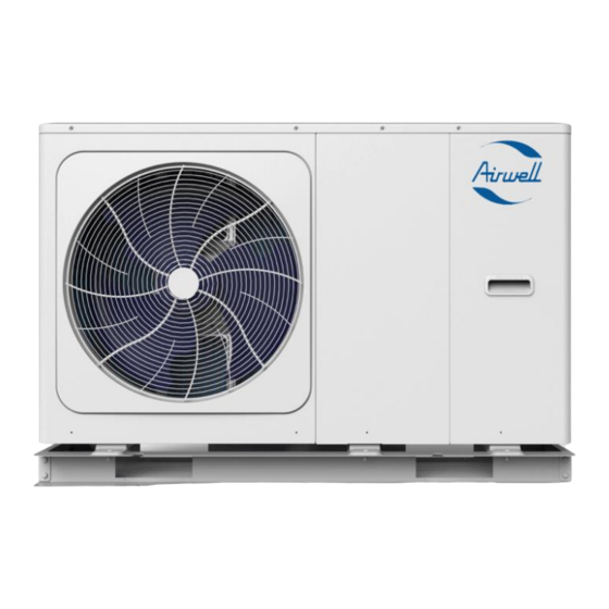
Airwell AW-WHPMA16-91 3ph Instalacja i konfiguracja - Strona 3
Przeglądaj online lub pobierz pdf Instalacja i konfiguracja dla Klimatyzator Airwell AW-WHPMA16-91 3ph. Airwell AW-WHPMA16-91 3ph 15 stron.

Please check the following before commencing start-up of the unit, as these are important conditions of the Airwell
Warranty*
•
The manufacture supplied filter has been installed to the return to the monobloc.
•
The system should be flushed, this is especially important if the system is an old gas or oil system. Flushing
should be completed in accordance to BS7593.
•
Airwell recommends a suitable heat transfer fluid is used to give a minimum frost protection of -12. In
order to stop bacterial growth, it is also recommended to use a suitable Biocide, if not included in the heat
transfer solution.
•
A 25lt buffer is Recommended for the 4-10kw units and a 40lt for the 12-16kw Airwell heat pumps, In order
to meet the minimum system water open volume at all times.
•
The pipe work diameter should be sized in relation to the length of the pipework run, number of fittings
and components but should have an internal bore no less than 28mm copper pipework. Be aware that
plastic pipework tends to have a smaller internal bore and needs to be sized correctly.
•
The external monobloc should be installed on a base suitable for withstanding the weight of the unit and
should be level. The steel plinth is Structural and
•
There shall be a proper means of disposal of the condensate, this should be via a drain or soak away.
•
The external monobloc unit should be positioned so that there is good air flow around the unit. The
minimum clearances are 300mm to the left, 600mm to the right, 300mm behind the unit and 1000mm in
front on the 4-6kw and 1500mm on the 8-16kw units.
*The Terms and Condition should be referred to for further information.
As part of the commissioning process, it is important that the correct flow rates are achieved for the output of the unit.
Unit
AW-WHPMA04-91
AW-WHPMA06-91
AW-WHPMA08-91
AW-WHPMA10-91
AW-WHPMA12-91
AW-WHPMA14-91
AW-WHPMA16-91
AW-WHPMA12-91 3ph
AW-WHPMA14-91 3ph
AW-WHPMA16-91 3ph
Failure to do so, will result in poor performance and protentional faults. The flow rates required are specified below.
*Please be aware if the only the minimum flow rate is achieved through the unit the unit will not function to its full output.
W: www.aukdistribution.com
Warranty
MUST NOT
be removed
Minimum Flow Rate
6.64 Lpm*
6.64 Lpm*
6.64 Lpm*
6.64 Lpm*
11.62 Lpm*
11.62 Lpm*
11.62 Lpm*
11.62 Lpm*
11.62 Lpm*
11.62Lpm*
T: 0191 516 6553
Maximum Flow Rate
14.16 Lpm
20.82 Lpm
27.48 Lpm
33.32 Lpm
41.65 Lpm
45.81 Lpm
49.98 Lpm
41.81 Lpm
45.81 Lpm
49.98 Lpm
