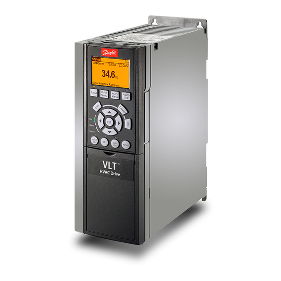
Danfoss VLT PROFIBUS DP MCA 101 Instrukcja instalacji - Strona 4
Przeglądaj online lub pobierz pdf Instrukcja instalacji dla Konwerter mediów Danfoss VLT PROFIBUS DP MCA 101. Danfoss VLT PROFIBUS DP MCA 101 6 stron. In automationdrive fc 361
Również dla Danfoss VLT PROFIBUS DP MCA 101: Instrukcja instalacji (20 strony)

Installation Guide | VLT® PROFIBUS DP MCA 101
4 Installation
4.1 Mounting
Procedure
1. Make sure that the power to the drive is disconnected.
2. Remove the front cover from the drive.
3. Remove the LCP (Local Control Panel) or blind cover, and then remove the LCP cradle from the drive.
4. Disconnect the communication cables from the existing MCA option card.
5. Remove the existing MCA option card from the drive.
6. Fit the new VLT® PROFIBUS DP MCA 101 option card into slot A. Mount the option with the connector facing up for top cable entry ,
or with the connector facing down for bottom cable entry. If an MCB option is installed, only top cable entry is possible.
7. Connect the communication cables.
8. Set the termination switch (shown in the illustration in
is the last station on the segment.
9. Set the address switches if needed.
10. Fit the LCP cradle.
11. Fit the LCP or blind cover in the LCP cradle.
12. Fit the front cover on the drive.
13. Connect power to the drive.
4.2 Setting Address Switches
Set the address switches to give the option a unique ID. Select an address range from 0–125 (factory setting 127) according to
Table 3: Settings for the Address Switches
Switch
Address value
5
35
82
Alternatively, assign a unique ID from parameter 9-18 Node Address. For setting the address from parameter 9-18 Node Address,
ensure that all address switches are set to ON. When the address is already set using address hardware switches, the address value
shown in parameter 9-18 Node Address is read-only.
4 | Danfoss A/S © 2019.03
8
7
Not used
+64
Not used
OFF
Not used
OFF
Not used
ON
4.2 Setting Address
Switches) on the fieldbus option to ON, when the drive
6
5
+32
+16
OFF
OFF
ON
OFF
OFF
ON
4
3
2
+8
+4
+2
OFF
ON
OFF
OFF
OFF
ON
OFF
OFF
ON
AN274235331989en-000101 / 130R0855
Installation
table
3.
1
+1
ON
ON
OFF
