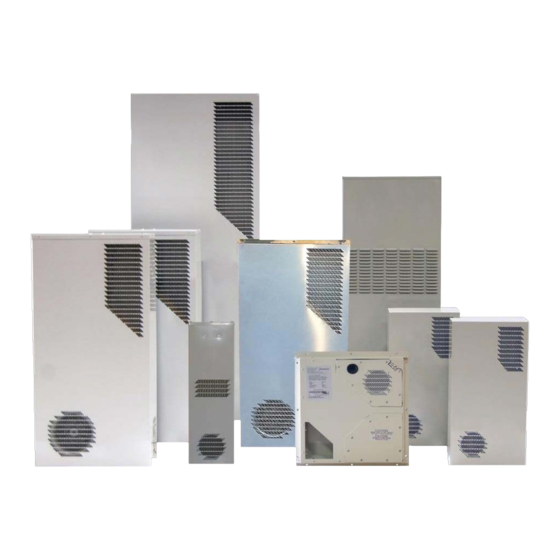
Dantherm Cooling PS023017Y Podręcznik z informacjami o produkcie - Strona 9
Przeglądaj online lub pobierz pdf Podręcznik z informacjami o produkcie dla Urządzenia przemysłowe Dantherm Cooling PS023017Y. Dantherm Cooling PS023017Y 14 stron.

- 1. Table of Contents
- 2. General Safety & Warning Instructions
- 3. Unpacking, Handling & Initial Inspection
- 4. Model Identification
- 5. Options
- 6. Product Drawings
- 7. Mounting of Unit to Enclosure & Operation
- 8. Design Data: General Performance
- 9. Maintenance
- 10. Warranty
- 11. Return Material Authorization Procedure
Dantherm Cooling , Inc. Heat Exchanger Operating & Maintenance Manual
6. MOUNTING OF UNIT TO ENCLOSURE & OPERATION
The enclosure shall be checked for correctness of cutouts, mounting holes and
electrical supply.
The Mounting Hook is preset to match the recommended cutout openings. If an
adjustment other than the factory setting of the hook needs to be made, do so prior
to fixing the gasket to the Heat Exchanger.
Install the gaskets as shown in section 5.1. A gasket kit is provided with each
unit. (Not required for PS018XXX-XX)
Remove the outer cover of the Heat Exchanger by removing the screws from
either the side or bottom of the unit. Depending on options selected, use a #2
Phillips Screwdriver, #20 Torx driver, or #15 Security Torx with pin driver. All
screw threads are M4.
Utilize an appropriate and safe lifting device.
Mount the Heat Exchanger to the cabinet by using the mounting hook, which
supports the weight of the unit. The hook grabs the cut out opening on the cabinet
panel.
Install the mounting hardware as supplied with the unit (M6 x 25 SCKT HD cap
screws & washers). The fixings are installed from inside the cabinet into the
threaded inserts located in the unit. Use 4mm Allen wrench / driver.
For PS018XXX-XX:
Place the unit for the inside of shelter through cutout opening using an appropriate
and safe lifting device.
Connect the Heat Exchanger power lead to the mains supply located in the
cabinet/enclosure. Refer to the product label on the bottom right hand side panel
of the unit for the proper voltage/amp requirement. Make sure a properly
grounded power supply is used. All installations are to be completed in
accordance with local NEC codes and guidelines.
The electrical circuit should be protected by a slow blow breaker or fuse. Refer to
section 5 in this manual for fuse/breaker rating.
After final installation and power supply connection the unit should powered and
the unit checked for correct airflow.
For PS0XX0XX-XX-S (Speed Control)
Push and hold test button located on control board for 5 seconds, to activate the
self test.
Check to correct airflow and fan speeds.
Please contact Dantherm for more information if required.
HexFlow Pinnacle Series Product Information Manual
Page 9 of 14
