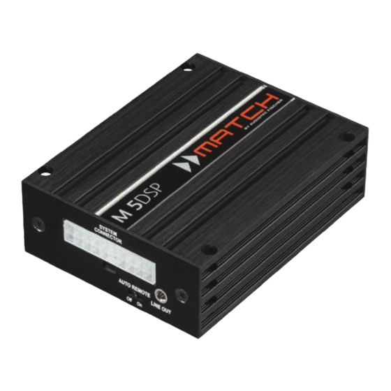
Audiotec Fischer Match M 5DSP Podręcznik - Strona 10
Przeglądaj online lub pobierz pdf Podręcznik dla Wzmacniacz Audiotec Fischer Match M 5DSP. Audiotec Fischer Match M 5DSP 16 stron. 5-channel, with integrated dsp

Installation with PP-ISO cable
To simplify installation to an OEM or aftermar-
ket radio the M 5DSP can also be connected us-
ing the optional PP-ISO cable (2.2 m version,
art. no. H424922). This cable allows to supply the
of the radio. No factory wires or plugs need to be cut
by using this connection method.
ATTENTION: In "HighPower" mode the power
supply of the M 5DSP must be connected di-
rectly to the car´s battery by using a separate
garding this note may result in damage of the
car audio system!
Connection to an OEM radio is detailed below:
1. After removing the car radio from the dash us-
ing appropriate tools, disconnect the vehicle
harness from the car radio. Next, connect the
vehicle harness to the female connector of the
Depending on your car an additional car-specif-
ic adaptor may be required.
A list of all cars and the respective adaptors can
be found on
2. Connect the male connector of the PP-ISO ca-
) to the car radio.
2
3. Subsequently connect the 20-pole connector of
4. There are two alternatives to connect the
M 5DSP to power described in section 4a and
4b.
ATTENTION: In "HighPower" mode alterna-
tive 4b must be used.
When connecting a subwoofer to the M 5DSP,
we also recommend to use alternative 4b. Short
interrupts in music reproduction at high listen-
vehicle cable harness dimension.
4a. Power supply via vehicle cable harness:
In this case the M 5DSP will be directly pow-
ered from the vehicle´s car radio harness. Care-
1
.
.
we strongly recommend option 4b.
Note: Depending on the vehicle type the con-
nections for switched (ACC+) positive terminal
and constant positive terminal can be inter-
changed. The M 5DSP must not be powered
using the switched positive terminal as this
might result in damage to the vehicle's elec-
must be made prior to activation of the unit at
connections
F
voltmeter. The constant positive wire is identi-
-
is turned off. After measuring connect cable
to the permanent positive terminal
Note: The yellow wires are connected ex fac-
tory.
If you are unable to identify the appropriate
wires please ask your dealer for help.
4b. Direct power supply via the battery:
This wiring option has to be used if
" HighPower" mode is activated! It may also
be necessary if a subwoofer is connected to the
cannot provided via the vehicle cable harness
(max. 20A).
To do so disconnect joints (black, ground) and
(yellow, +12 V) of the PP-ISO cable harness
(
). Next, the ground cable (black,
4
) should be connected to a common
3
ground reference point (this is located where
the negative terminal of the battery is grounded
to the metal body of the vehicle) or to a pre-
pared metal location on the vehicle chassis i.e.
an area which has been cleaned of all paint res-
idues by using a power wire with a wire gauge
of min. 4 mm² / AWG 12. Always disconnect
the car battery's negative terminal before
you execute the following steps. Connect
4 mm² / AWG 12) to the positive terminal of the
battery. The positive wire from the battery to the
M 5DSP harness connection needs to have a
main fuse (min. 30 A) at a distance of no more
than 12 inches (30 cm) from the battery. Insu-
late the now unused connections of th PP-ISO
appropriate material.
You can now reconnect the car battery. If one
(yellow) and
(blue) with a
G
3
) with tape or other
4
H
.
/ min.
23
