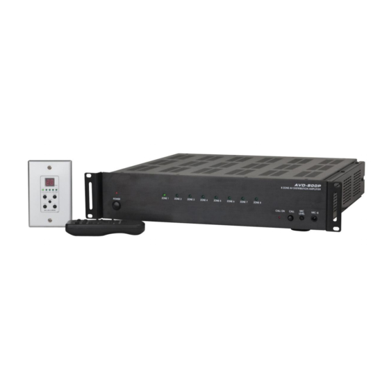
DAPAudio D2680 Instrukcja obsługi produktu - Strona 8
Przeglądaj online lub pobierz pdf Instrukcja obsługi produktu dla Wzmacniacz DAPAudio D2680. DAPAudio D2680 16 stron. 8 zones multiroom system

Backpanel
8. Preamp Line Out (1-8)
If an application requires more power than the built in zone poweramp (2x20W) can deliver, you
can use the zone line outputs to connect an additional amplifier.
9. Zone Speaker Output (zone 1-8)
Four pole terminal for connecting 2 speakers to a zone.
Make sure that the minimum speaker load is 4 Ω.
10. Inter Data Loop
You can loop up to 16 units giving you a maximum of 128 zones using this connector. Also see fig. 4.
11. Control Pad
This connector is used for linking purposes when using more than 2 units and is wired in parallel with
the Inter Data Loop (10) connector. Also see figure 4.
12. Call LED
Use this connector to connect an optional Call LED Display Box.
13. AC-selector switch
Check the setting of this switch. The switch should always be set to the mains voltage used in your
country.
14. Input Source Loop In/ Out
Use these connectors to loop the 10 audio/ video sources when using several units by using an IDC
flatcable.
15. Video Camera Input
Use to connect up to 4 composite (analog) camera's by means of a suitable BNC -> Cat 5 adapter.
Camera's can be monitored in sequence by pressing the Master Scan (44) Button on your remote
control.
16. Zone Audio/ Video Input
You can connect 4 audio/ video sources selectable by using the keypad. Press the Select (26) button
until the Function LED (24) light then select the source C1-C6 using the Up (29) and Down (28) buttons.
17. Zone Audio Input
You can connect 2 audio sources selectable by using the keypad. Press the select button until
the Function LED light then select the source C1-C6 using the Up (29) and Down (28) buttons.
18. Keypad (zone1-8)
You can connect up to 8 keypads to a single device.
19. AGC/ Address Select
If linking more than one device you have to set each device to its own address. See the section on
DIP switch settings on page 7.
20. IR Remote Emitter (1-8)
Use these outputs to connect an optional IR link cable.
21.
External Mute
Use an external signal between 3Vdc and 12Vdc to mute all zones.
22.
SYS Trigger
The SYS Trigger output will be 12Vdc (High) if at least one zone is powered on. If all zones are powered
off, the output will be 0Vdc (Low).
6
Fig. 2
